background image

Troubleshooting

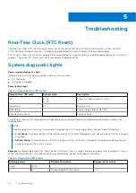
Real-Time Clock (RTC Reset)

The Real Time Clock (RTC) reset function allows you or the service technician to recover Dell Inspiron, systems from No
POST/No Power/No Boot situations. The legacy jumper enabled RTC reset has been retired on these models.

Start the RTC reset with the system powered off and connected to AC power. Press and hold the power button for thirty (30)
seconds. The system RTC Reset occurs after you release the power button.

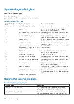
System diagnostic lights

Power-supply diagnostics light

Indicates the status of the power-supply in either of the two sates:

Off: No Power

On: Power is supplied.

Power button light

Table 4. Power button LED status 

Power button LED state

System state

Description

Off

S4

S5

There is in Hibernate or Off state.

Solid White

S0

Working state

Solid Amber

Various sleep states or No POST

Blinking Amber/White

Failure to POST

This platform relies on the Power button LED light blinking in an amber/white pattern to determine a failure as listed in the
following table:

NOTE:

The blinking patterns consists of two numbers (representing First Group: Amber blinks, Second Group: White blinks).

First Group

: The Power button LED light blinks Amber, 1 to 9 times followed by a short pause with LED off for a couple

of seconds.

Second Group

: The Power button LED light then blinks White, 1 to 9 times, followed by a longer pause before the next

cycle starts again after a short interval.

.

Example

: No Memory detected (2,3). Power button LED blinks 2-times in Amber followed by a pause, and then blinks 3-times in

White. The Power button LED will pause for few seconds before the next cycle repeats itself again.

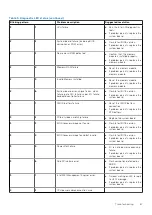
Table 5. Diagnostic LED status 

Blinking pattern

Problem description

Suggested resolution

Amber

White

1

2

Unrecoverable SPI flash failure

5

66

Troubleshooting

Summary of Contents for Vostro 3881

Page 1: ...Vostro 3881 Service Manual Regulatory Model D29M Regulatory Type D29M002 August 2021 Rev A01 ...

Page 2: ...tial damage to hardware or loss of data and tells you how to avoid the problem WARNING A WARNING indicates a potential for property damage personal injury or death 2020 2021 Dell Inc or its subsidiaries All rights reserved Dell EMC and other trademarks are trademarks of Dell Inc or its subsidiaries Other trademarks may be trademarks of their respective owners ...

Page 3: ...1 Major components of your system 3 ...

Page 4: ...Major components of your system 4 Major components of your system ...

Page 5: ...e assembly 4 Fan shroud 5 Heatsink assembly 6 3 5 inch hard drive 7 Memory module 8 Media card reader 9 Power button switch 10 Front bezel 11 Chassis 12 System board 13 Graphics card 14 Processor 15 Power supply unit Major components of your system 5 ...

Page 6: ... device to go into standby without needing to refresh its memory Deep power down mode is expected to reduce standby power consumption by 40 to 50 percent DDR4 Details There are subtle differences between DDR3 and DDR4 memory modules as listed below Key notch difference The key notch on a DDR4 module is in a different location from the key notch on a DDR3 module Both notches are on the insertion ed...

Page 7: ... USB 3 1 Gen 1 Port 5 Gbps SuperSpeed 2010 USB 3 1 Gen 2 10 Gbps SuperSpeed 2013 USB 3 0 USB 3 1 Gen 1 SuperSpeed USB For years the USB 2 0 has been firmly entrenched as the de facto interface standard in the PC world with about 6 billion devices sold and yet the need for more speed grows by ever faster computing hardware and ever greater bandwidth demands The USB 3 0 USB 3 1 Gen 1 finally has the...

Page 8: ... 2 0 connection could ever come close to the 480Mbps theoretical maximum throughput making data transfer at around 320 Mbps 40 MB s the actual real world maximum Similarly USB 3 0 USB 3 1 Gen 1 connections will never achieve 4 8Gbps We will likely see a real world maximum rate of 400MB s with overheads At this speed USB 3 0 USB 3 1 Gen 1 is a 10x improvement over USB 2 0 Applications USB 3 0 USB 3...

Page 9: ...ple The USB Power Delivery specification ups this power delivery to 100 watts It s bi directional so a device can either send or receive power And this power can be transferred at the same time the device is transmitting data across the connection This could spell the end of all those proprietary laptop charging cables with everything charging via a standard USB connection You could charge your la...

Page 10: ...between display and source devices enabling a TV to optimize picture settings based on content type Additional Color Spaces Adds support for additional color models used in digital photography and computer graphics 4K Support Enables video resolutions far beyond 1080p supporting next generation displays that will rival the Digital Cinema systems used in many commercial movie theaters HDMI Micro Co...

Page 11: ...ructions that is shipped with the product or at www dell com regulatory_compliance CAUTION Before touching anything inside your computer ground yourself by touching an unpainted metal surface such as the metal at the back of the computer While you work periodically touch an unpainted metal surface to dissipate static electricity which could harm internal components CAUTION When you disconnect a ca...

Page 12: ...e electrical potential This is done through the use of a field service electrostatic discharge ESD kit When connecting a bonding wire ensure that it is connected to bare metal and never to a painted or non metal surface The wrist strap should be secure and in full contact with your skin and ensure that you remove all jewelry such as watches bracelets or rings prior to bonding yourself and the equi...

Page 13: ... recommended to test the wrist strap and bonding wire at least once per week ESD Wrist Strap Tester The wires inside of an ESD strap are prone to damage over time When using an unmonitored kit it is a best practice to regularly test the strap prior to each service call and at a minimum test once per week A wrist strap tester is the best method for doing this test If you do not have your own wrist ...

Page 14: ... sensitive components After working inside your computer About this task CAUTION Leaving stray or loose screws inside your computer may severely damage your computer Steps 1 Replace all screws and ensure that no stray screws remain inside your computer 2 Connect any external devices peripherals or cables you removed before working on your computer 3 Replace any media cards discs or any other parts...

Page 15: ...box This is to ensure that the correct number of screws and correct screw type is restored when the component is replaced NOTE Some computers have magnetic surfaces Ensure that the screws are not left attached to such surface when replacing a component NOTE Screw color may vary with the configuration ordered Table 2 Screw list Component Screw type Quantity Image Side cover 6 32 2 M 2 2230 2280 Sol...

Page 16: ...equisites 1 Follow the procedure in Before working on your computer NOTE Ensure that the security cable is removed from the security cable slot if applicable About this task The following images indicate the location of the side cover and provide a visual representation of the removal procedure 16 Disassembly and reassembly ...

Page 17: ...and remove the side cover off the chassis Installing the side cover Prerequisites If you are replacing a component remove the existing component before performing the installation process About this task The following image indicates the location of the side cover and provides a visual representation of the installation procedure Disassembly and reassembly 17 ...

Page 18: ...he slots on the chassis and slide it towards the front of the computer 2 Tighten the two thumb screws 6 32 to secure the side cover to the chassis Next steps 1 Follow the procedure in After working inside your computer 18 Disassembly and reassembly ...

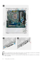
Page 19: ...l and provide a visual representation of the removal procedure Steps 1 Gently pry and release the front cover tabs sequentially from the top 2 Rotate the front cover outward from the chassis 3 Remove the front bezel from the computer Installing the front bezel Prerequisites If you are replacing a component remove the existing component before performing the installation process Disassembly and rea...

Page 20: ... until the tabs clicks into place and tighten the three hooks in place Next steps 1 Install the side cover 2 Follow the procedure in After working inside your computer Fan shroud Removing the fan shroud Prerequisites 1 Follow the procedure in Before working on your computer 2 Remove the side cover About this task The following images indicate the location of the fan duct and provide a visual repre...

Page 21: ...d remove the fan duct from the computer Installing the fan shroud Prerequisites If you are replacing a component remove the existing component before performing the installation process About this task The following image indicates the location of the fan shroud and provides a visual representation of the installation procedure Disassembly and reassembly 21 ...

Page 22: ...ps 1 Install the side cover 2 Follow the procedure in After working inside your computer Memory modules Removing the memory modules Prerequisites 1 Follow the procedure in Before working on your computer 2 Remove the side cover About this task The following images indicate the location of the memory modules and provide a visual representation of the removal procedure 22 Disassembly and reassembly ...

Page 23: ...ot NOTE If the memory module is difficult to remove gently ease the memory module back and forth to remove it from the slot Installing the memory modules Prerequisites If you are replacing a component remove the existing component before performing the installation process About this task NOTE Caution To prevent damage to the memory module hold the memory module by the edges Do not touch the compo...

Page 24: ...e down until it clicks into place NOTE The securing clips return to the locked position If you do not hear the click remove the memory module and reinstall it NOTE Repeat step 1 to step 3 when installing more than one memory module in your computer Next steps 1 Install the side cover 2 Follow the procedure in After working inside your computer Hard drive assembly Removing the primary 2 5 inch hard...

Page 25: ... inch hard drive NOTE For primary 2 5 inch hard drive the other end of the data cable is connected to the SATA0 connector on the system board 2 Press both the release tabs on the hard drive assembly to free it from the mounting points on the chassis 3 Bring the assembly forward to free the lower side of the assembly from the chassis NOTE Note the orientation of the hard drive so that you can repla...

Page 26: ...s a visual representation of the installation procedure Steps 1 Place the hard drive assembly on the mounting point at the bottom of the chassis 2 Press the release tabs on the hard drive assembly and push the assembly back into place to secure it to the chassis 3 Reconnect the data and power cables to the 2 5 inch hard drive Next steps 1 Install the front bezel 2 Install the side cover 3 Follow t...

Page 27: ...he following images indicate the location of the 2 5 inch hard drive and provides a visual representation of the removal procedure Steps 1 Remove the two M3x3 5 screws that secure the first hard drive to the hard drive assembly 2 Lift and slide the hard drive from the hard drive assembly 3 Remove the two M3x3 5 screws that secure the second hard drive to the hard drive assembly 4 Lift and slide th...

Page 28: ...the first hard drive into the hard drive assembly and align the slots on the bracket with the slots on the hard drive 2 Replace the two M3x3 5 screws to secure the first hard drive to the hard drive assembly 3 Place the second hard drive into the hard drive assembly and align the slots on the bracket with the slots on the hard drive 4 Replace the two M3x3 5 screws to secure the second hard drive t...

Page 29: ...the 3 5 inch hard drive assembly and provides a visual representation of the removal procedure Steps 1 Disconnect the data and power cables from the 3 5 inch hard drive 2 Remove the four 6 32 screws that secure the 3 5 inch hard drive 3 Lift the hard drive assembly away from the chassis Installing the 3 5 inch hard drive assembly Prerequisites If you are replacing a component remove the existing c...

Page 30: ...4 Route the power cable and data cable through the routing guides on the hard drive assembly and connect the cables to the hard drive Next steps 1 Install the side cover 2 Follow the procedure in After working inside your computer Solid state drive Removing the M 2 2230 solid state drive Prerequisites 1 Follow the procedure in Before working on your computer 2 Remove the side cover About this task...

Page 31: ...em board Installing the M 2 2230 solid state drive Prerequisites If you are replacing a component remove the existing component before performing the installation process About this task The following image indicates the location of the M 2 2230 solid state drive and provides a visual representation of the installation procedure Disassembly and reassembly 31 ...

Page 32: ...em board Next steps 1 Install the side cover 2 Follow the procedure in After working inside your computer Removing the M 2 2280 solid state drive Prerequisites 1 Follow the procedure in Before working on your computer 2 Remove the side cover About this task The following images indicate the location of the M 2 2280 solid state drive and provide a visual representation of the removal procedure 32 D...

Page 33: ...em board Installing the M 2 2280 solid state drive Prerequisites If you are replacing a component remove the existing component before performing the installation process About this task The following image indicates the location of the M 2 2280 solid state drive and provides a visual representation of the installation procedure Disassembly and reassembly 33 ...

Page 34: ...eps 1 Install the side cover 2 Follow the procedure in After working inside your computer Coin cell battery Installing the coin cell battery Prerequisites If you are replacing a component remove the existing component before performing the installation process About this task The following image indicates the location of the coin cell battery and provides a visual representation of the installatio...

Page 35: ...etup program s settings to default It is recommended that you note the BIOS setup program s settings before removing the battery NOTE After a service incident where the system board is replaces or when the coin cell battery is replaced an RTC reset cycle will occur When an RTC Reset cycle occurs the computer turns on and off three times An Invalid Configuration error message is displayed prompting...

Page 36: ... system board Wireless card Removing the wireless card Prerequisites 1 Follow the procedure in Before working on your computer 2 Remove the side cover 3 Remove the powered GPU NOTE This step is required only if the system is configured with powered GPU About this task The following images indicate the location of the wireless card and provide a visual representation of the removal procedure 36 Dis...

Page 37: ...4 Slide and remove the wireless card at an angle from the wireless card slot Installing the wireless card Prerequisites If you are replacing a component remove the existing component before performing the installation process About this task The following image indicates the location of the wireless card and provides a visual representation of the installation procedure Disassembly and reassembly ...

Page 38: ...ry black triangle Black 2 Slide and place the wireless card bracket on the wireless card 3 Align the notch on the wireless card with the tab on the wireless card slot 4 Slide the wireless card at an angle into the wireless card slot 5 Replace the screw M2x3 that secures the wireless card to the system board Next steps 1 Install the Powered GPU NOTE This step is required only if the system is confi...

Page 39: ... 2 Remove the side cover About this task The following images indicate the location of the graphics card and provides a visual representation of the removal procedure Steps 1 Lay the computer with its right side facing down 2 Locate the graphics card installed in the PCIe x16 card slot 3 Lift the pull tab and open the expansion card door Disassembly and reassembly 39 ...

Page 40: ...following images indicate the location of the graphics card and provides a visual representation of the installation procedure Steps 1 Align the graphics card with the PCIe x16 card slot on the system board 2 Using the alignment post connect the card in the connector and press down firmly Ensure that the card is firmly seated 3 Close the expansion card door Next steps 1 Install the side cover 2 Fo...

Page 41: ...e the side cover NOTE Note the routing of all cables as you remove them so that you can route them correctly while you are replacing the power supply unit About this task The following images indicate the location of the power supply unit and provides a visual representation of the removal procedure Disassembly and reassembly 41 ...

Page 42: ... power supply from the chassis 5 Slide and lift the power supply from its slot on the chassis Installing the power supply unit Prerequisites If you are replacing a component remove the existing component before performing the installation procedure WARNING The cables and ports on the back of the power supply unit are color coded to indicate the different power wattage Ensure that you plug in the c...

Page 43: ...Disassembly and reassembly 43 ...

Page 44: ...rd NOTE The power supply cable is connected to the system board at two locations and supply power to the following components at the two location Processor ATX CPU connector System board ATX SYS connector Next steps 1 Install the side cover 2 Follow the procedure in After working inside your computer Optical drive Removing the optical drive Prerequisites 1 Follow the procedure in Before working on...

Page 45: ...ion tab to release the optical drive 3 Slide and remove the optical drive from the front slot on the chassis Installing the optical drive Prerequisites If you are replacing a component remove the existing component before performing the installation procedure About this task The following images indicate the location of the optical drive and provide a visual representation of the installation proc...

Page 46: ...e the optical drive to the chassis 3 Connect the optical drive power cable to the connector on the optical drive 4 Connect the optical drive data cable to the connector on the optical drive Next steps 1 Install the side cover 2 Follow the procedure in After working inside your computer 46 Disassembly and reassembly ...

Page 47: ...drive bezel and provides a visual representation of the removal procedure Steps Pry the bezel from the optical drive Installing the optical drive bezel Prerequisites If you are replacing a component remove the existing component before performing the installation procedure About this task The following images indicate the location of optical drive bezel and provides a visual representation of the ...

Page 48: ...s 1 Follow the procedure in Before working on your computer WARNING The heat sink may become hot during normal operation Allow sufficient time for the heat sink to cool before touching it CAUTION For maximum cooling of the processor do not touch the heat transfer areas on the heat sink The oils in your skin can reduce the heat transfer capability of the thermal grease 2 Remove the side cover 3 Rem...

Page 49: ...t sink assembly Prerequisites If you are replacing a component remove the existing component before performing the installation process About this task NOTE If either the processor or the fan and heat sink assembly is replaced use the thermal grease provided in the kit to ensure that thermal conductivity is maintained The following image indicates the location of the fan and heat sink assembly and...

Page 50: ...e to the connector on the system board Next steps 1 Install the fan shroud 2 Install the side cover 3 Follow the procedure in After working inside your computer Processor Removing the processor Prerequisites 1 Follow the procedure in Before working on your computer 2 Remove the side cover 3 Remove the fan shroud 4 Remove the fan and heat sink assembly NOTE Caution The processor may become hot duri...

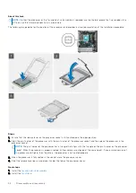
Page 51: ...Press the release lever down and then push it away from the processor to release it from the securing tab 2 Lift the lever upward to lift the processor cover CAUTION When removing the processor do not touch any of the pins inside the socket or allow any objects to fall on the pins in the socket 3 Gently lift the processor from its socket on the system board Installing the processor Prerequisites I...

Page 52: ...pin 1 corner of the processor socket and then place the processor in the processor socket NOTE The pin 1 corner of the processor has a triangle that aligns with the triangle on the pin 1 corner on the processor socket When the processor is properly seated all four corners are aligned at the same height If one or more corners of the processor are higher than the others the processor is not seated p...

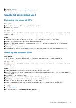
Page 53: ...ard slot Installing the powered GPU Prerequisites If you are replacing a component remove the existing component before performing the installation procedure About this task The following images indicate the location of the powered graphical processing unit and provides a visual representation of the installation procedure Steps 1 Align the powered GPU with the PCI Express card connector on the sy...

Page 54: ...nstallation process About this task The following image indicates the location of the speakers and provides a visual representation of the installation procedure Steps 1 Press and slide the speaker in the slot on the chassis until it snaps into place 2 Route the speaker cable through the routing guide on the chassis 3 Connect the speaker cable to the connector on the system board Next steps 1 Inst...

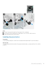
Page 55: ...assis 3 Remove the power button out from the chassis Installing the power button Prerequisites If you are replacing a component remove the existing component before performing the installation procedure About this task The following images indicate the location of the power button and provides a visual representation of the installation procedure Disassembly and reassembly 55 ...

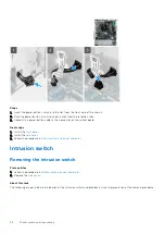
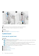
Page 56: ...t steps 1 Install the front bezel 2 Install the side cover 3 Follow the procedure in After working inside your computer Intrusion switch Removing the intrusion switch Prerequisites 1 Follow the procedure in Before working on your computer 2 Remove the side cover About this task The following images indicate the location of the intrusion switch and provides a visual representation of the removal pr...

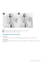
Page 57: ...ssis Installing the intrusion switch Prerequisites If you are replacing a component remove the existing component before performing the installation procedure About this task The following images indicate the location of the intrusion switch and provides a visual representation of the installation procedure Disassembly and reassembly 57 ...

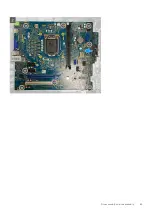
Page 58: ... enter the Service Tag in the BIOS setup program after you replace the system board NOTE Replacing the system board removes any changes that you have made to the BIOS using the BIOS setup program You must make the appropriate changes again after you replace the system board NOTE Before disconnecting the cables from the system board note the location of the connectors so that you can reconnect the ...

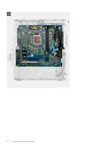
Page 59: ... and heat sink assembly 9 Remove the processor About this task The following images indicate the location of the system board and provides a visual representation of the removal procedure Disassembly and reassembly 59 ...

Page 60: ...60 Disassembly and reassembly ...

Page 61: ...the front I O bracket to the chassis 2 Slide and remove the front I O bracket from the chassis 3 Disconnect the following cables that are connected to the system board and remove them from the routing points on the chassis Disassembly and reassembly 61 ...

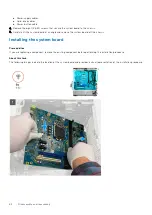
Page 62: ...angle and remove the system board off the chassis Installing the system board Prerequisites If you are replacing a component remove the existing component before performing the installation procedure About this task The following images indicate the location of the system board and provides a visual representation of the installation procedure 62 Disassembly and reassembly ...

Page 63: ...Disassembly and reassembly 63 ...

Page 64: ...s align with the ones on the system board 2 Replace the eight screws 6 32 that secure the system board to the chassis 3 Using the routing points on the chassis route and reconnect the following cables to the connectors on the system board Power supply cables 64 Disassembly and reassembly ...

Page 65: ...y 4 Install the graphics card 5 Install the M 2 2230 SSD M 2 2280 SSD 6 Install the memory module 7 Install the front bezel 8 Install the Side cover 9 Follow the procedure in After working inside your computer NOTE Your computer s Service Tag is stored in the system board You must enter the Service Tag in the BIOS setup program after you replace the system board NOTE Replacing the system board rem...

Page 66: ... Amber Various sleep states or No POST Blinking Amber White Failure to POST This platform relies on the Power button LED light blinking in an amber white pattern to determine a failure as listed in the following table NOTE The blinking patterns consists of two numbers representing First Group Amber blinks Second Group White blinks First Group The Power button LED light blinks Amber 1 to 9 times fo...

Page 67: ...A20 failure super I O failure keyboard controller failure Flash latest BIOS version If problem persists replace the system board 3 1 CMOS battery failure Reset the CMOS battery connection If problem persists replace the RTS battery 3 2 PCIe or video card chip failure Replace the system board 3 3 BIOS recovery image not found Flash latest BIOS version If problem persists replace the system board 3 ...

Page 68: ...ace the system board 3 1 CMOS battery failure Reset the CMOS battery connection If problem persists replace the RTS battery 3 2 PCIe or video card chip failure Replace the system board 3 3 BIOS recovery image not found Flash latest BIOS version If problem persists replace the system board 3 4 BIOS recovery image found but invalid Flash latest BIOS version If problem persists replace the system boa...

Page 69: ...A20 FAILURE A memory module may be loose Reinstall the memory module or if necessary replace it GENERAL FAILURE The operating system is unable to carry out the command The message is usually followed by specific information For example Printer out of paper Take the appropriate action HARD DISK DRIVE CONFIGURATION ERROR The computer cannot identify the drive type Shut down the computer remove the h...

Page 70: ...ory module or if necessary replace it MEMORY ALLOCATION ERROR The software you are attempting to run is conflicting with the operating system another program or a utility Shut down the computer wait for 30 seconds and then restart it Run the program again If the error message still appears see the software documentation MEMORY DOUBLE WORD LOGIC FAILURE AT ADDRESS READ VALUE EXPECTING VALUE A memor...

Page 71: ...system setup program does not match the system clock Correct the settings for the Date and Time options TIMER CHIP COUNTER 2 FAILED A chip on the system board may be malfunctioning Run the System Set tests in Dell Diagnostics UNEXPECTED INTERRUPT IN PROTECTED MODE The keyboard controller may be malfunctioning or a memory module may be loose Run the System Memory tests and the Keyboard Controller t...

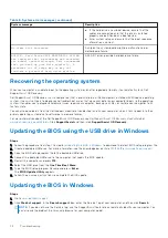
Page 72: ...e You can also download it from the Dell Support website to troubleshoot and fix your computer when it fails to boot into their primary operating system due to software or hardware failures For more information about the Dell SupportAssist OS Recovery see Dell SupportAssist OS Recovery User s Guide at www dell com serviceabilitytools Click SupportAssist and then click SupportAssist OS Recovery Upd...

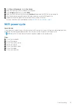
Page 73: ...ions For more information see knowledge base article 000124211 at www dell com support WiFi power cycle About this task If your computer is unable to access the internet due to WiFi connectivity issues a WiFi power cycle procedure may be performed The following procedure provides the instructions on how to conduct a WiFi power cycle NOTE Some ISPs Internet Service Providers provide a modem router ...

Page 74: ...r Express Service Code at www dell com support For more information on how to find the Service Tag for your computer see Locate the Service Tag on your computer Dell knowledge base articles for a variety of computer concerns 1 Go to www dell com support 2 On the menu bar at the top of the Support page select Support Knowledge Base 3 In the Search field on the Knowledge Base page type the keyword t...
Reviews: