background image

Adding and Replacing Parts

107

4

Disconnect your computer and all attached devices from their electrical outlets.

5

Remove the battery. 
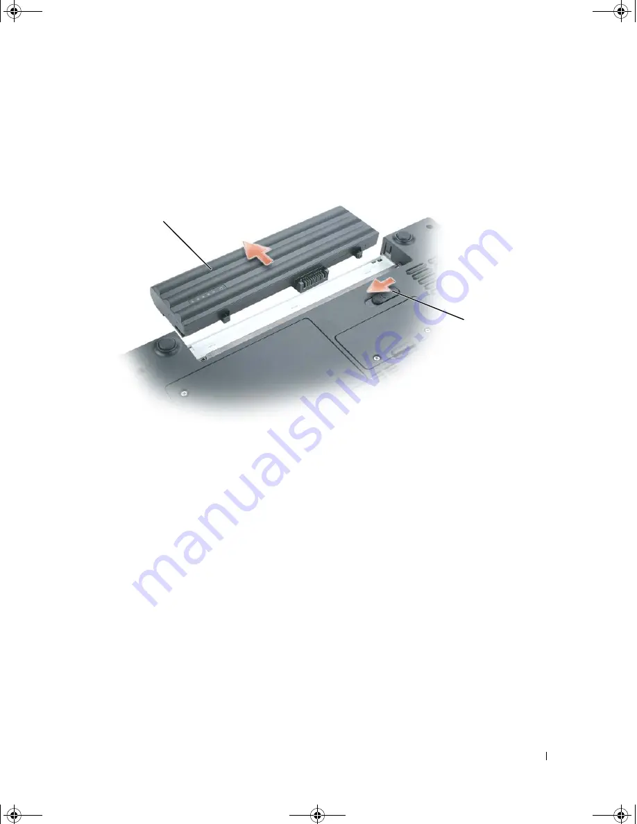
Slide and hold the battery-bay latch release on the bottom of the computer, and then pull the 

battery out of the battery bay.

6

Remove the optical drive, if installed, from the optical drive bay. See "Optical Drives" on 

page 111.

7

Press the power button to ground the system board. 

8

Remove any installed ExpressCards from the ExpressCard slot. See "Removing an 

ExpressCard or Blank" on page 68.

9

Remove any installed media memory cards from the 5-in-1 media memory card reader. See 

"Removing a Media Memory Card or Blank" on page 72.

10

Close the display and turn the computer upside down on a flat work surface.

11

Remove the hard drive. See "Hard Drive" on page 108. 

1

battery

2

battery-bay latch release

2

1

book.book  Page 107  Wednesday, October 26, 2005  1:00 PM

Summary of Contents for studio XPS

Page 1: ...w w w d e l l c o m s u p p o r t d e l l c o m Dell Portable Computers Owner s Manual Model PP19L book book Page 1 Wednesday October 26 2005 1 00 PM ...

Page 2: ... Trademarksusedinthistext Dell theDELLlogo Inspiron DellPrecision Dimension DellNet OptiPlex Latitude PowerEdge PowerConnect PowerVault PowerApp Dell TravelLite ExpressCharge and Strike Zone are trademarks of Dell Inc Intel Celeron and Pentium are registered trademarks of Intel Corporation Microsoft Outlook and Windows are registered trademarks of Microsoft Corporation Bluetooth is a registered tr...

Page 3: ...tion 25 Transferring Information to a New Computer 26 Running the Files and Settings Transfer Wizard With the Operating System CD 27 Running the Files and Settings Transfer Wizard Without the Operating System CD 27 Setting Up a Printer 29 Printer Cable 29 Connecting a USB Printer 30 Power Protection Devices 30 Surge Protectors 31 Line Conditioners 31 Uninterruptible Power Supplies 31 book book Pag...

Page 4: ...ooth Wireless Technology 36 Power Management 37 Speaker Functions 37 Microsoft Windows Logo Key Functions 37 Touch Pad 38 Customizing the Touch Pad 38 5 Power Management Power Management Tips 39 Power Management Wizard 39 Setting Sleep Modes 39 Selecting a Power Scheme 40 Setting Battery Alarms and Actions 41 Completing the Power Management Wizard 41 Power Management Modes 41 Standby Mode 41 Hiber...

Page 5: ... Windows Power Meter 46 Charge Gauge 47 Health Gauge 47 Low Battery Warning 47 Charging the Battery 47 Storing a Battery 48 7 Using CDs DVDs and Other Multimedia Playing a CD or DVD 49 Adjusting the Volume 51 Adjusting the Picture 52 Copying CDs and DVDs 52 How to Copy a CD or DVD 52 Using Blank CDs and DVDs 53 Helpful Tips 54 Using Dell MediaDirect 54 Connecting Your Computer to a TV or Audio Dev...

Page 6: ...d Reader Media Memory Card Types 71 Media Memory Card Blanks 71 Installing a Media Memory Card 71 Removing a Media Memory Card or Blank 72 10 Setting Up a Home and Office Network Connecting to a Network Adapter 73 Network Setup Wizard 73 Connecting to a Wireless Local Area Network 74 Determining Your Network Type 74 Connecting to a Wireless Network in Microsoft Windows XP 74 11 Solving Problems De...

Page 7: ...icrosoft Windows operating system 89 A solid blue screen appears 89 Dell MediaDirect problems 89 Other software problems 90 Memory Problems 90 Network Problems 91 ExpressCard Problems 91 Power Problems 91 Ensuring Sufficient Power for Your Computer 92 Printer Problems 92 Scanner Problems 93 Sound and Speaker Problems 94 No sound from integrated speakers 94 No sound from external speakers 94 No sou...

Page 8: ... Tools 105 Turning Off Your Computer 105 Before Working Inside Your Computer 106 Battery 108 Removing a Battery 108 Installing a Battery 108 Hard Drive 108 Returning a Hard Drive to Dell 111 Optical Drives 111 About the Device Security Screw 111 Removing and Installing Optical Drives 111 Memory 112 Installing a Memory Module in Connector DIMM B 113 Installing a Memory Module in Connector DIMM A 11...

Page 9: ...creen 137 System Setup Screen 138 Commonly Used Options 138 Computer Tracking Software 139 Traveling With Your Computer 139 Identifying Your Computer 139 Packing the Computer 139 Travel Tips 140 Traveling by Air 140 If Your Computer Is Lost or Stolen 141 Cleaning Your Computer 141 Computer Keyboard and Display 141 Touch Pad 142 Floppy Drive 142 CDs and DVDs 142 FCC Notices U S Only 142 Class A 143...

Page 10: ...port Policy U S Only 144 Definition of Dell Installed Software and Peripherals 144 Definition of Third Party Software and Peripherals 145 Contacting Dell 145 Glossary 163 Index 175 book book Page 10 Wednesday October 26 2005 1 00 PM ...

Page 11: ...ed on your computer You can use the CD to reinstall drivers see page 97 or to run the Dell Diagnostics see page 77 Readme files may be included on your CD to provide last minute updates about technical changes to your computer or advanced technical reference material for technicians or experienced users NOTE Drivers and documentation updates can be found at support dell com How to set up my comput...

Page 12: ... Service Tag and Express Service Code Microsoft Windows License Label Service Tag and Microsoft Windows License These labels are located on the bottom of your computer Use the Service Tag to identify your computer when you use support dell com or contact technical support Enter the Express Service Code to direct your call when contacting technical support What Are You Looking For Find It Here book...

Page 13: ...should also reinstall the NSS utility NSS provides critical updates for your operating system and support for Dell 3 5 inch USB floppy drives Intel Pentium M processors optical drives and USB devices NSS is necessary for correct operation of your Dell computer The software automatically detects your computer and operating system and installs the updates appropriate for your configuration To downlo...

Page 14: ...stalled on your computer To reinstall your operating system use the Operating System CD See Reinstalling Windows XP on page 103 After you reinstall your operating system use the Drivers and Utilities CD ResourceCD to reinstall drivers for the devices that came with your computer NOTE The color of your CD varies based on the operating system you ordered What Are You Looking For Find It Here book bo...

Page 15: ...latch release 5 touch pad 9 keyboard 2 display 6 media control buttons 10 keyboard and wireless status lights 3 power button 7 speakers 11 display latches 2 4 device status lights 8 touch pad buttons 1 9 2 5 8 3 7 10 4 6 11 book book Page 15 Wednesday October 26 2005 1 00 PM ...

Page 16: ...connected to an electrical outlet the light operates as follows Solid green The battery is charging Flashing green The battery is almost fully charged If the computer is running on a battery the light operates as follows Off The battery is adequately charged or the computer is turned off Flashing orange The battery charge is low Solid orange The battery charge is critically low Turns on when you t...

Page 17: ...7 TOUCH PAD BUTTONS Touch pad buttons provide the functionality of a mouse KEYBOARD The keyboard includes a numeric keypad as well as the Microsoft Windows logo key For information on supported keyboard shortcuts see Key Combinations on page 36 Mute the sound Turn the volume down Turn the volume up Play or pause Play the previous track Play the next track Stop Launch Dell MediaDirect or Microsoft ...

Page 18: ...is enabled To enable or disable wireless networking press Fn F2 Turns on when a card with Bluetooth wireless technology is enabled NOTE The card with Bluetooth wireless technology is an optional feature so the light turns on only if you ordered the card with your computer For more information see the documentation that came with your card To turn off only the Bluetooth wireless technology function...

Page 19: ... work with the security cable slot SECURITY CABLE SLOT Lets you attach a commercially available antitheft device to the computer For more information see the instructions included with the device AIR VENT The computer uses fans to create airflow through the vents which prevents the computer from overheating 1 security cable slot 4 IEEE 1394 connector 7 5 in 1 media memory card reader 2 air vent 5 ...

Page 20: ...5 in 1 media memory card reader reads the following digital media memory cards Secure Digital SD card SDIO MultiMediaCard MMC Memory Stick Memory Stick PRO xD Picture Card EXPRESSCARD SLOT Supports one ExpressCard The computer ships with a plastic blank installed in the slot For more information see Using ExpressCards on page 67 Connects your computer to a TV Also connects digital audio capable de...

Page 21: ... the computer do not plug a telephone line into the network connector 1 optical drive bay 3 USB connectors 2 5 network connector RJ 45 2 optical drive tray eject button 4 modem connector RJ 11 6 video connector Connect USB devices such as a mouse keyboard or printer You can also connect the optional floppy drive directly to a USB connector using the optional floppy drive cable To use the internal ...

Page 22: ...s the computer to a network The green and yellow lights next to the connector indicate activity for wired network communications For information on using the network adapter see the online network adapter documentation supplied with your computer Connects an external VGA compatible monitor 1 USB connectors 2 2 AC adapter connector Connect USB devices such as a mouse keyboard or printer You can als...

Page 23: ... the computer to an electrical outlet For more information see Using a Battery on page 45 MEMORY MODULE COVER Covers the compartment that contains the memory modules For more information see page 112 BATTERY BAY LATCH RELEASE Releases the battery from the battery bay See Battery on page 108 FAN The computer uses a fan to create airflow through the vents which prevents the computer from overheating...

Page 24: ...al drive in the optical drive bay For more information see Optical Drives on page 111 HARD DRIVE Stores software and data For more information see Hard Drive on page 108 and Hard drive problems on page 81 The size displayed for your hard drive in Windows Explorer is the capacity of the drive before any operating system or programs are installed BATTERY CHARGE GAUGE Provides information on the batt...

Page 25: ...lephone line to the modem connector on your computer and to the telephone wall jack before you set up your Internet connection If you are using a DSL or cable modem connection contact your ISP for setup instructions Setting Up Your Internet Connection To set up an Internet connection with a provided ISP desktop shortcut 1 Save and close any open files and exit any open programs 2 Double click the ...

Page 26: ...our ISP to check the service status or try connecting again later Transferring Information to a New Computer The Microsoft Windows XP operating system provides a Files and Settings Transfer Wizard to move data from a source computer to a new computer You can transfer data such as E mail messages Toolbar settings Window sizes Internet bookmarks You can transfer the data to the new computer over a n...

Page 27: ...Transfer Wizard welcome screen click Next 5 On the Which computer is this screen click Old Computer and click Next 6 On the Select a transfer method screen click the transfer method you prefer 7 On the What do you want to transfer screen select the items you want to transfer and click Next After the information has been copied the Completing the Collection Phase screen appears 8 Click Finish To tr...

Page 28: ...letes and the Now go to your old computer message appears do not click Next 8 Go to the old computer To copy data from the old computer 1 On the old computer insert the wizard disk 2 Click the Start button and click Run 3 In the Open field on the Run window browse to the path for fastwiz on the appropriate removable media and click OK 4 On the Files and Settings Transfer Wizard welcome screen clic...

Page 29: ...OTE Access to the Dell Knowledge Base document may not be available in some countries Setting Up a Printer NOTICE Complete the operating system setup before you connect a printer to the computer See the documentation that came with the printer for setup information including how to Obtain and install updated drivers Connect the printer to the computer Load paper and install the toner or ink cartri...

Page 30: ...nnectors fit only one way 3 Turn on the printer and then turn on the computer If the Add New Hardware Wizard window appears click Cancel 4 Install the printer driver if necessary See the documentation that came with your printer Power Protection Devices Several devices are available to protect against power fluctuations and failures Surge protectors Line conditioners Uninterruptible power supplies...

Page 31: ...r documentation for modem connection instructions NOTICE Not all surge protectors offer network adapter protection Disconnect the network cable from the network wall jack during electrical storms Line Conditioners NOTICE Line conditioners do not protect against power interruptions Line conditioners are designed to maintain AC voltage at a fairly constant level Uninterruptible Power Supplies NOTICE...

Page 32: ...32 Setting Up Your Computer w w w d e l l c o m s u p p o r t d e l l c o m book book Page 32 Wednesday October 26 2005 1 00 PM ...

Page 33: ...hange the brightness level the Brightness Meter appears but the brightness level on the monitor does not change You can enable or disable the Brightness Meter from the QuickSet taskbar menu When the meter is enabled press the following keys to adjust brightness Press Fn and the up arrow key to increase brightness on the integrated display only not on an external monitor Press Fn and the down arrow...

Page 34: ...eference If you choose a resolution or color palette that is higher than the display supports the settings adjust automatically to the closest supported values 1 Click the Start button and click Control Panel 2 Under Pick a category click Appearance and Themes 3 Under Pick a task click the area you want to change or under or pick a Control Panel icon click Display 4 Try different settings for Colo...

Page 35: ...pad has multiple functions The keypad numbers and symbols are marked in blue on the right of the keypad keys To type a number or symbol press Fn and the desired key after enabling the keypad To enable the keypad press Num Lk The light indicates that the keypad is active To disable the keypad press Num Lk again 1 numeric keypad 1 9 book book Page 35 Wednesday October 26 2005 1 00 PM ...

Page 36: ... tray out of the drive if Dell QuickSet is installed This feature is not supported in Dell MediaDirect For more information on QuickSet see Dell QuickSet Features on page 44 Fn F8 Switches the video image to the next display option The options include the integrated display an external monitor and both displays simultaneously Fn and up arrow key Increases brightness on the integrated display only ...

Page 37: ...ncreases the volume of the integrated speakers and external speakers if attached Fn Page Dn Decreases the volume of the integrated speakers and external speakers if attached Fn End Enables and disables the integrated speakers and external speakers if attached Windows logo key and m Minimizes all open windows Windows logo key and Shift m Maximizes all windows Windows logo key and e Runs Windows Exp...

Page 38: ...e your finger on the touch pad and move the selected object by sliding your finger over the surface To double click an object position the cursor on the object and tap twice on the touch pad or use your thumb to press the left touch pad button twice Customizing the Touch Pad You can use the Mouse Properties window to disable the touch pad or adjust their settings 1 Open the Control Panel click Pri...

Page 39: ...you have restricted access rights Click or double click the icon to open the Power Management Wizard The first two screens of the wizard Welcome and What is Power Management describe and define various power management options NOTE On the What is Power Management screen you can select Do not show this page again When you select this option the Welcome screen also does not appear again Use the scre...

Page 40: ... Dell QuickSet predefined power schemes Maximum Battery Maximum Performance Presentation and Network Disabled NOTE QuickSet automatically adds the word QuickSet after the names of power schemes created using QuickSet All QuickSet power schemes are displayed in a drop down menu near the center of the screen The power settings for each scheme are below the name of the current selection The power set...

Page 41: ...have selected and click Finish For more information about QuickSet right click the icon in the taskbar and click Help Power Management Modes Standby Mode Standby mode conserves power by turning off the display and the hard drive after a predetermined period of inactivity a time out When the computer exits standby mode it returns to the same operating state it was in before entering standby mode NO...

Page 42: ...o exit hibernate mode press the power button The computer may take a short time to exit hibernate mode You cannot make the computer exit hibernate mode by pressing a key or touching the touch pad For more information on hibernate mode see the documentation that came with your operating system Power Options Properties The Power Options Properties window helps you to manage power consumption and mon...

Page 43: ...dvanced Tab The Advanced tab allows you to Set power icon and standby mode password options Select how the computer will respond when you close the display Choose no action Enter standby mode Enter hibernate mode Select how the computer will respond when you press the power button Choose no action Enter standby mode Enter hibernate mode Shut down Microsoft Windows and turn off the computer Prompt ...

Page 44: ...lbars Select a power scheme that you set in the Power Management Wizard see page 39 Turn presentation mode on or off Double Clicking the QuickSet Icon Double click the icon to adjust power management settings using the Power Management Wizard see page 39 Right Clicking the QuickSet Icon Right click the icon to perform the following tasks Enable or disable the Brightness Meter on the screen see pag...

Page 45: ...let the first time you use the computer For best results operate the computer with the AC adapter until the battery is fully charged To view battery charge status access the Control Panel Power Options Power Meter tab Battery operating time varies depending on operating conditions NOTE Battery operating time the time the battery can hold a charge decreases over time Depending on how often the batt...

Page 46: ... with extreme care Damaged batteries may leak and cause personal injury or equipment damage Checking the Battery Charge The Dell QuickSet Battery Meter the Microsoft Windows Power Meter window and icon the battery charge gauge and the low battery warning provide information on the battery charge Dell QuickSet Battery Meter If Dell QuickSet is installed press Fn F3 to display the QuickSet Battery M...

Page 47: ...e mode begins automatically A pop up window warns you when the battery charge is approximately 90 percent depleted For more information about low battery alarms see Power Management on page 39 Charging the Battery NOTE Without Dell ExpressCharge the AC adapter charges a completely discharged 6 cell battery in approximately 2 hours and a 9 cell battery in approximately 3 hours with the computer tur...

Page 48: ... Storing a Battery Remove the battery when you store your computer for an extended period of time A battery discharges during prolonged storage After a long storage period recharge the battery fully before you use it book book Page 48 Wednesday October 26 2005 1 00 PM ...

Page 49: ... closed when you are not using the drive NOTICE Do not move the computer when you are playing CDs or DVDs to prevent damage to your CD DVD drive or discs 1 Press the eject button on the front of the drive 2 Pull out the tray 3 Place the disc label side up in the center of the tray and snap the disc onto the spindle 1 CD DVD tray 1 book book Page 49 Wednesday October 26 2005 1 00 PM ...

Page 50: ... CDs for storing data to create music CDs or to copy CDs see the CD software that came with your computer NOTE Ensure that you follow all copyright laws when you create CDs The CD player includes the following basic buttons The DVD player includes the following basic buttons Play Move backward within the current track Move forward within the current track Go to the previous track Go to the next tr...

Page 51: ...lick Help in the Volume Control window The Volume Meter displays the current volume level including mute on your computer Either right click the icon in the taskbar or press the volume control buttons to enable or disable the Volume Meter on the screen When the Volume Meter is enabled adjust the volume with the volume control buttons or by pressing the following key combinations Press Fn PageUp to...

Page 52: ...D drives offered by Dell may vary by country The following instructions explain how to make an exact copy of a CD or DVD You can also use Sonic DigitalMedia for other purposes such as creating music CDs from audio files stored on your computer or backing up important data For help open Sonic DigitalMedia and then click the question mark icon in the upper right corner of the window How to Copy a CD...

Page 53: ... while DVD writable drives can write to both CD and DVD recording media Use blank CD Rs to record music or permanently store data files After creating a CD R you cannot write to that CD R again see the Sonic documentation for more information Use blank CD RWs to write to CDs or to erase rewrite or update data on CDs Blank DVD Rs can be used to permanently store large amounts of information After y...

Page 54: ...again You can also use blank CD RWs to test music file projects before you record the project permanently to a blank CD R See the Sonic website at www sonic com for additional information Using Dell MediaDirect NOTE Dell QuickSet which is automatically installed and enabled on your computer is necessary for Dell MediaDirect to function Changing or disabling QuickSet default settings can limit Dell...

Page 55: ...luded with your computer Cables may be purchased at most consumer electronics stores The TV digital audio adapter cable is available for purchase from Dell Your computer has an S video TV out connector that together with a standard S video cable available from Dell enables you to connect the computer to a TV 1 Dell MediaDirect button 1 S video TV out connector 3 S PDIF digital audio connector 5 S ...

Page 56: ...e the diagrams at the beginning of each subsection to help you determine which method of connection you should use S video and standard audio Composite video and standard audio When you finish connecting the video and audio cables between your computer and your TV you must enable your computer to work with the TV See Enabling the Display Settings for a TV on page 66 to ensure that the computer rec...

Page 57: ...er 3 Plug the other end of the S video cable in to the S video input connector on your TV 4 Plug the single connector end of the audio cable in to the headphone connector on your computer 5 Plug the two RCA connectors on the other end of the audio cable in to the audio input connectors on your TV or other audio device 1 TV digital audio adapter cable 2 standard S video cable 3 standard audio cable...

Page 58: ...le and then turn on the computer 7 See Enabling the Display Settings for a TV on page 66 to ensure that the computer recognizes and works properly with the TV S Video and S PDIF Digital Audio 1 S video TV out connector 1 TV digital audio adapter cable 2 S video cable 3 S PDIF digital audio cable 1 1 2 3 book book Page 58 Wednesday October 26 2005 1 00 PM ...

Page 59: ...ther end of the S video cable in to the S video input connector on the TV 5 Plug one end of the S PDIF digital audio cable in to the digital audio connector on the TV digital audio adapter cable 6 Plug the other end of the S PDIF digital audio cable in to the audio input connector on your TV or other audio device 1 S video cable 2 S PDIF digital audio cable 1 TV digital audio adapter cable 2 S vid...

Page 60: ... on the computer 8 See Enabling the Display Settings for a TV on page 66 to ensure that the computer recognizes and works properly with the TV Composite Video and Standard Audio 1 audio input connector 2 composite video input connector 1 TV digital audio adapter cable 2 composite video cable 3 standard audio cable 2 1 1 2 3 book book Page 60 Wednesday October 26 2005 1 00 PM ...

Page 61: ...mposite video input connector on the TV 5 Plug the single connector end of the audio cable in to the headphone connector on the computer 6 Plug the two RCA connectors on the other end of the audio cable in to the audio input connectors on your TV or other audio device 7 Turn on the TV turn on any audio device that you connected if applicable and then turn on the computer 8 See Enabling the Display...

Page 62: ... l c o m s u p p o r t d e l l c o m Composite Video and S PDIF Digital Audio 1 composite video input connector 1 TV digital audio adapter cable 2 composite video cable 3 standard audio cable 1 1 2 3 book book Page 62 Wednesday October 26 2005 1 00 PM ...

Page 63: ...one end of the S PDIF digital audio cable in to the S PDIF audio connector on the TV digital audio adapter cable 6 Plug the other end of the digital audio cable in to the S PDIF input connector on your TV or other audio device 7 Turn on the TV turn on any audio device that you connected if applicable and then turn on the computer 8 See Enabling the Display Settings for a TV on page 66 to ensure th...

Page 64: ...werDVD application 2 Insert a DVD into the DVD drive If the DVD begins playing click the stop button 3 Click the Settings option 4 Click the DVD option 5 Click the DVD Audio Setting icon 6 Click the arrows beside the Speaker Configuration setting to scroll through the options and select the SPDIF option 7 Click the Back button once and then click the Back button again to return to the main menu sc...

Page 65: ... for DVD playback 1 Click Start Programs PowerDVD to launch the Cyberlink PowerDVD program 2 Insert a DVD into the DVD drive If the DVD begins playing click the stop button 3 Click the Settings option 4 Click the DVD option 5 Click the DVD Audio Setting icon 6 Click the arrows beside the Speaker Configuration setting to scroll through the options and select the Headphones option 7 Click the arrows...

Page 66: ...gs and then click Control Panel 2 Double click Display and click the Settings tab 3 Click Advanced 4 Click the tab for your video card 5 In the display devices section select the appropriate option for using either a single display or multiple displays ensuring that the display settings are correct for your selection NOTE To determine the type of video card installed in your computer click the Sta...

Page 67: ... The computer automatically detects the card ExpressCards are generally marked with a symbol such as a triangle or an arrow or a label to indicate which end to insert into the slot The cards are keyed to prevent incorrect insertion If card orientation is not clear see the documentation that came with the card CAUTION Before you begin any of the procedures in this section follow the safety instruct...

Page 68: ...d and stop it from functioning before you remove it from the computer If you do not stop the card in the configuration utility you could lose data CAUTION Before you begin any of the procedures in this section follow the safety instructions in the Product Information Guide Press the latch and remove the card or blank For some latches you must press the latch twice once to pop the latch out and the...

Page 69: ...Using ExpressCards 69 1 release button 2 ExpressCard 1 2 book book Page 69 Wednesday October 26 2005 1 00 PM ...

Page 70: ...70 Using ExpressCards w w w d e l l c o m s u p p o r t d e l l c o m book book Page 70 Wednesday October 26 2005 1 00 PM ...

Page 71: ...om dust and other particles Save the blank for use when no card is installed in the slot blanks from other computers may not fit your computer To remove the blank see Removing a Media Memory Card or Blank on page 72 Installing a Media Memory Card You can install a media memory card in the computer while the computer is running The computer automatically detects the card Media memory cards are gene...

Page 72: ...t came with the media memory card if applicable Removing a Media Memory Card or Blank NOTICE Use the media memory card configuration utility click the icon in the taskbar to select a card and stop it from functioning before you remove it from the computer If you do not stop the card in the configuration utility you could lose data CAUTION Before you begin any of the procedures in this section foll...

Page 73: ...cure 2 Connect the other end of the network cable to a network connection device such as a network wall connector NOTE Do not use a network cable with a telephone wall connector Network Setup Wizard The Microsoft Windows XP operating system provides a Network Setup Wizard to guide you through the process of sharing files printers or an Internet connection between computers in a home or small offic...

Page 74: ... ad hoc network does not use routers or access points and consists of computers that broadcast to one another For additional assistance with setting up your wireless connection go to support dell com and search for the keyword wireless setup Connecting to a Wireless Network in Microsoft Windows XP Your wireless network card requires specific software and drivers in order to connect to a network Th...

Page 75: ...ea NOTE The following instructions apply if you use the Windows operating system to manage your network devices For information about other wireless configuration utilities see your wireless network documentation 1 Click either the pop up or the network icon to configure your computer for one of the available wireless networks The Wireless Network Connections window lists the wireless networks ava...

Page 76: ...rk security settings are unique to your network Dell cannot provide this information NOTE Your computer can take up to 1 minute to connect to a network After your computer is configured for the wireless network you selected another pop up notifies you that your computer is connected to the network you selected Thereafter whenever you log on to your computer in the area of the wireless network the ...

Page 77: ...iagnostics From Your Hard Drive The Dell Diagnostics is located on a hidden diagnostic utility partition on your hard drive NOTE If your computer cannot display a screen image contact Dell See Contacting Dell on page 145 1 Shut down the computer 2 Connect the computer to an electrical outlet 3 Diagnostics can be invoked one of two ways a Turn on the computer When the DELL logo appears press F12 im...

Page 78: ...rivers and Utilities CD NOTE The Drivers and Utilities CD may be optional and may not ship with your computer 1 Insert the Drivers and Utilities CD 2 Shut down and restart the computer When the DELL logo appears press F12 immediately If you wait too long and the Windows logo appears continue to wait until you see the Windows desktop Then shut down your computer and try again NOTE The next steps ch...

Page 79: ...formation Option Function Express Test Performs a quick test of devices This test typically takes 10 to 20 minutes and requires no interaction on your part Run Express Test first to increase the possibility of tracing the problem quickly Extended Test Performs a thorough check of devices This test typically takes 1 hour or more and requires you to answer questions periodically Custom Test Tests a ...

Page 80: ...nother floppy disk CD or DVD to eliminate the possibility that the original one is defective Insert a bootable floppy disk and restart the computer CLEAN THE DRIVE OR DISK See Cleaning Your Computer on page 141 ENSURE THAT THE CD IS SNAPPED ONTO THE SPINDLE CHECK THE CABLE CONNECTIONS CHECK FOR HARDWARE INCOMPATIBILITIES See Resolving Software and Hardware Incompatibilities on page 99 RUN THE DELL...

Page 81: ...software If you cannot eject the CD CD RW DVD or DVD RW drive tray 1 Ensure that the computer is shut down 2 Straighten a paper clip and insert one end into the eject hole at the front of the drive push firmly until the tray is partially ejected 3 Gently pull out the tray until it stops If you hear an unfamiliar scraping or grinding sound Ensure that the sound is not caused by the program that is ...

Page 82: ...the telephone line connector into the modem Disconnect the telephone line from the modem and connect it to a telephone Listen for a dial tone If you have other telephone devices sharing the line such as an answering machine fax machine surge protector or line splitter then bypass them and connect the modem directly to the telephone wall jack If you are using a line that is 3 m 10 ft or more in len...

Page 83: ...up program If the problem persists contact Dell See Contacting Dell on page 145 BAD COMMAND OR FILE NAME Ensure that you have spelled the command correctly put spaces in the proper place and used the correct pathname CACHE DISABLED DUE TO FAILURE The primary cache internal to the microprocessor has failed Contact Dell See Contacting Dell on page 145 CD DRIVE CONTROLLER FAILURE The CD drive does no...

Page 84: ...nostics see page 77 HARD DISK DRIVE FAILURE The hard drive does not respond to commands from the computer Shut down the computer remove the hard drive see page 108 and boot the computer from a CD Then shut down the computer reinstall the hard drive and restart the computer If the problem persists try another drive Run the Hard Disk Drive tests in the Dell Diagnostics see page 77 HARD DISK DRIVE RE...

Page 85: ...12 MEMORY DOUBLE WORD LOGIC FAILURE AT ADDRESS READ VALUE EXPECTING VALUE A memory module may be faulty or improperly seated Reinstall the memory modules and if necessary replace them see page 112 MEMORY ODD EVEN LOGIC FAILURE AT ADDRESS READ VALUE EXPECTING VALUE A memory module may be faulty or improperly seated Reinstall the memory modules and if necessary replace them see page 112 MEMORY WRITE...

Page 86: ...rical outlet to charge the battery If the problem persists try to restore the data by entering the system setup program Then immediately exit the program See Using the System Setup Program on page 137 If the message reappears contact Dell See Contacting Dell on page 145 TIME OF DAY CLOCK STOPPED The reserve battery that supports the system configuration settings may require recharging Connect your...

Page 87: ... Information Guide NOTE Use the integrated keyboard when running the Dell Diagnostics or the system setup program When you attach an external keyboard the integrated keyboard remains fully functional External Keyboard problems NOTE When you attach an external keyboard the integrated keyboard remains fully functional CHECK THE KEYBOARD CABLE Shut down the computer Disconnect the keyboard cable and ...

Page 88: ... NUMERIC KEYPAD Press Num Lk to disable the numeric keypad if numbers are displayed instead of letters Verify that the numbers lock light is not lit Lockups and Software Problems CAUTION Before you begin any of the procedures in this section follow the safety instructions in the Product Information Guide The computer does not start up ENSURE THAT THE AC ADAPTER IS FIRMLY CONNECTED TO THE COMPUTER ...

Page 89: ...elp TO PLAY MOVIES WITH DELL MEDIADIRECT YOU MUST HAVE A DVD DRIVE AND THE DELL DVD PLAYER If you purchased a DVD drive with your computer this software should already be installed VIDEO QUALITY PROBLEMS Turn off the Use Hardware Acceleration option This feature takes advantage of the special processing in some graphics cards to reduce processor requirements when playing DVDs and certain types of ...

Page 90: ...r might be infected with spyware Use an anti virus program that includes anti spyware protection your program may require an upgrade to scan the computer and remove spyware For more information go to support dell com and search for the keyword spyware RUN THE DELL DIAGNOSTICS If all tests run successfully the error condition is related to a software problem See Dell Diagnostics on page 77 Memory P...

Page 91: ...uct Information Guide CHECK THE EXPRESSCARD Ensure that the ExpressCard is properly inserted into the connector ENSURE THAT THE CARD IS RECOGNIZED BY WINDOWS Double click the Safely Remove Hardware icon in the Windows taskbar Ensure that the card is listed IF YOU HAVE PROBLEMS WITH A DELL PROVIDED EXPRESSCARD Contact Dell See Contacting Dell on page 145 IF YOU HAVE PROBLEMS WITH AN EXPRESSCARD NOT...

Page 92: ...HE AC ADAPTER Check the AC adapter cable connections If the AC adapter has a light ensure that the light is on CONNECT THE COMPUTER DIRECTLY TO AN ELECTRICAL OUTLET Bypass power protection devices power strips and the extension cable to verify that the computer turns on ELIMINATE POSSIBLE INTERFERENCE Turn off nearby fans fluorescent lights halogen lamps or other appliances ADJUST THE POWER PROPER...

Page 93: ...Problems CAUTION Before you begin any of the procedures in this section follow the safety instructions in the Product Information Guide NOTE If you need technical assistance for your scanner contact the scanner s manufacturer CHECK THE PRINTER DOCUMENTATION See the printer documentation for setup and troubleshooting information CHECK THE SCANNER DOCUMENTATION See the scanner documentation for setu...

Page 94: ... corner of your screen Ensure that the volume is turned up and that the sound is not muted DISCONNECT HEADPHONES FROM THE HEADPHONE CONNECTOR Sound from the speakers is automatically disabled when headphones are connected to the computer s front panel headphone connector TEST THE ELECTRICAL OUTLET Ensure that the electrical outlet is working by testing it with another device such as a lamp ELIMINA...

Page 95: ... procedures in this section follow the safety instructions in the Product Information Guide If the display is blank NOTE If you are using a program that requires a higher resolution than your computer supports it is recommended that you attach an external monitor to your computer CHECK THE BATTERY If you are using a battery to power your computer the battery charge may be depleted Connect the comp...

Page 96: ...k the area you want to change or click the Display icon 4 Try different settings for Color quality and Screen resolution SEE ERROR MESSAGES If an error message appears see page 83 If only part of the display is readable CONNECT AN EXTERNAL MONITOR 1 Shut down your computer and connect an external monitor to the computer 2 Turn on the computer and the monitor and adjust the monitor brightness and c...

Page 97: ...has an exclamation point a yellow circle with a on the device icon If an exclamation point is next to the device name you may need to reinstall the driver or install a new driver See Reinstalling Drivers and Utilities on page 97 Reinstalling Drivers and Utilities NOTICE The Dell Support website at support dell com and your Drivers and Utilities CD provide approved drivers for Dell computers If you...

Page 98: ... your preferred language for the driver or utility if available A welcome screen appears 4 Click Next The CD automatically scans your hardware to detect drivers and utilities used by your computer 5 After the CD completes the hardware scan you can also detect other drivers and utilities Under Search Criteria select the appropriate categories from the System Model Operating System and Topic drop do...

Page 99: ...d the driver files 9 When the name of the appropriate driver appears click Next 10 Click Finish and restart your computer Resolving Software and Hardware Incompatibilities If a device is either not detected during the operating system setup or is detected but incorrectly configured you can use the Hardware Troubleshooter to resolve the incompatibility To start the Hardware Troubleshooter 1 Click t...

Page 100: ...gular backups of your data files System Restore does not monitor your data files or recover them NOTE The procedures in this document were written for the Windows default view so they may not apply if you set your Dell computer to the Windows Classic view Creating a Restore Point 1 Click the Start button and click Help and Support 2 Click the task for System Restore 3 Follow the instructions on th...

Page 101: ...ailable System Restore is automatically disabled To see if System Restore is enabled 1 Click the Start button and click Control Panel 2 Click Performance and Maintenance 3 Click System 4 Click the System Restore tab 5 Ensure that Turn off System Restore is unchecked Using Dell PC Restore by Symantec NOTICE Using Dell PC Restore permanently deletes all data on the hard drive and removes any applica...

Page 102: ...appear such as the End User License Agreement are the same ones that appeared the first time the computer was turned on 7 Click Next The System Restore screen appears and the computer restarts 8 After the computer restarts click OK Removing Dell PC Restore NOTICE Removing Dell PC Restore from the hard drive permanently deletes the PC Restore utility from your computer After you have removed Dell P...

Page 103: ...If Device Driver Rollback does not resolve the problem then use System Restore to return your operating system to the operating state it was in before you installed the new device driver See Using Microsoft Windows XP System Restore on page 100 To reinstall Windows XP you need the following items Dell Operating System CD Dell Drivers and Utilities CD NOTE The Drivers and Utilities CD contains driv...

Page 104: ...ge appears 3 Restart the computer 4 Press F2 immediately after the DELL logo appears If the operating system logo appears wait until you see the Windows desktop and then shut down the computer and try again 5 Press the arrow keys to select CD ROM and press Enter 6 When the Press any key to boot from CD message appears press any key 7 When the Windows XP Setup screen appears press Enter 8 Follow th...

Page 105: ...llowing tools Small flat blade screwdriver Phillips screwdriver Small plastic scribe Flash BIOS update see the Dell Support website at support dell com Turning Off Your Computer NOTICE To avoid losing data save and close any open files and exit any open programs before you turn off your computer 1 Shut down the operating system a Save and close any open files exit any open programs click the Start...

Page 106: ...tor or on its strain relief loop not on the cable itself Some cables have a connector with locking tabs if you are disconnecting this type of cable press in on the locking tabs before you disconnect the cable As you pull connectors apart keep them evenly aligned to avoid bending any connector pins Also before you connect a cable ensure that both connectors are correctly oriented and aligned NOTICE...

Page 107: ...rives on page 111 7 Press the power button to ground the system board 8 Remove any installed ExpressCards from the ExpressCard slot See Removing an ExpressCard or Blank on page 68 9 Remove any installed media memory cards from the 5 in 1 media memory card reader See Removing a Media Memory Card or Blank on page 72 10 Close the display and turn the computer upside down on a flat work surface 11 Rem...

Page 108: ...your Dell computer Do not use a battery from other computers with your computer Slide the battery into the bay until the latch release clicks Hard Drive CAUTION If you remove the hard drive from the computer when the drive is hot do not touch the metal housing of the hard drive CAUTION Before you begin any of the procedures in this section follow the safety instructions in the Product Information ...

Page 109: ...Protecting Against Electrostatic Discharge in the Product Information Guide 3 Lift the cover off the computer and set it aside 4 Use the pull tab to slide the hard drive toward the screw holes and then lift the hard drive straight up to remove it from the computer 1 screws 2 1 book book Page 109 Wednesday October 26 2005 1 00 PM ...

Page 110: ...y damage the connector 6 Seat the new hard drive into the bay and then slide it into the connector by sliding it away from the screw holes until it is fully seated 7 Replace the cover and tighten the screws 8 Install the operating system for your computer See Restoring Your Operating System on page 99 9 Install the drivers and utilities for your computer See Reinstalling Drivers and Utilities on p...

Page 111: ...ely When you install a module in the bay you can install the device security screw to prevent the module from being easily removed Removing and Installing Optical Drives NOTICE To prevent damage to drives store them in a safe dry place when they are not installed in the computer Avoid pressing down on them or placing heavy objects on top of them 1 While the computer is turned on double click the S...

Page 112: ...ystem board See Specifications on page 131 for information on the memory supported by your computer Install only memory modules that are intended for your computer NOTE Memory modules purchased from Dell are covered under your computer warranty CAUTION Before you begin any of the procedures in this section follow the safety instructions in the Product Information Guide The computer has two memory ...

Page 113: ... Connector DIMM B 1 Follow the procedures in Before You Begin on page 105 2 Ground yourself by touching one of the metal connectors on the back of the computer NOTE If you leave the area ground yourself again when you return to the computer 3 Turn the computer over loosen the captive screws on the memory module cover and then remove the memory module cover 1 screws 2 2 memory module cover 1 2 book...

Page 114: ...odule in the connector labeled DIMM A before you install a module in the connector labeled DIMM B Insert memory modules at a 45 degree angle to avoid damaging the connector NOTE If the memory module is not installed properly the computer may not boot properly No error message indicates this failure 5 Ground yourself and install the new memory module a Align the notch in the module edge connector w...

Page 115: ...additional memory and automatically updates the system configuration information To confirm the amount of memory installed in the computer click the Start button click Help and Support and then click Computer Information Installing a Memory Module in Connector DIMM A The memory module connector labeled DIMM A is located under the keyboard 1 Follow the procedures in Before You Begin on page 105 2 G...

Page 116: ...ews on the memory module cover and then remove the memory module cover NOTICE To prevent damage to the memory module connector do not use tools to spread the memory module securing clips 6 If you are replacing a memory module remove the existing module a Use your fingertips to carefully spread apart the securing clips on each end of the memory module connector until the module pops up b Remove the...

Page 117: ...not installed properly the computer may not boot properly No error message indicates this failure 7 Ground yourself and install the new memory module a Align the notch in the module edge connector with the tab in the connector slot b Slide the module firmly into the slot at a 45 degree angle and rotate the module down until it clicks into place If you do not feel the click remove the module and re...

Page 118: ...two screws inside the battery bay as part of the hinge replacement procedure 11 Insert the battery into the battery bay or connect the AC adapter to your computer and an electrical outlet 12 Reinstall the hard drive See Hard Drive on page 108 13 Turn on the computer As the computer boots it detects the additional memory and automatically updates the system configuration information To confirm the ...

Page 119: ...ore you begin any of the procedures in this section follow the safety instructions in the Product Information Guide 1 Follow the procedures in Before You Begin on page 105 2 Turn the computer over loosen the captive screws on the modem Mini PCI wireless cover and then remove the cover 1 modem Mini PCI wireless cover 1 book book Page 119 Wednesday October 26 2005 1 00 PM ...

Page 120: ...all the replacement modem a Connect the modem cable to the modem NOTICE The connectors are keyed to ensure correct insertion If you feel resistance check the connectors and realign the card b Align the modem with the screw holes and press the modem into the connector on the system board c Replace the screw that secures the modem to the system board 5 Replace the modem Mini PCI wireless cover 1 scr...

Page 121: ...on Guide 1 Follow the procedures in Before You Begin on page 105 2 If a Mini PCI card is not already installed go to step If you are replacing a Mini PCI card remove the existing card a Disconnect the antenna cables from the Mini PCI card b Release the Mini PCI card by spreading the metal securing tabs until the card pops up slightly c Lift the Mini PCI card out of its connector 1 antenna cables 1...

Page 122: ...damaging the Mini PCI card make sure the antenna cables are not under the card when you click the card into place a Align the Mini PCI card with the connector at a 45 degree angle and press the Mini PCI card into the connector until it clicks b Connect the antenna cables to the Mini PCI card Make sure the cables snap onto the tiny connectors on the Mini PCI card 1 Mini PCI card 2 metal securing ta...

Page 123: ...on follow the safety instructions in the Product Information Guide NOTICE To avoid electrostatic discharge ground yourself by using a wrist grounding strap or by periodically touching an unpainted metal surface such as a connector on the back of the computer 1 antenna cables 1 book book Page 123 Wednesday October 26 2005 1 00 PM ...

Page 124: ...e hinge cover 1 Follow the procedures in Before You Begin on page 105 2 Remove the battery see page 108 3 Remove the two screws inside the battery bay 4 Turn the computer right side up and then open the display all the way 180 degrees so that it rests on your work surface NOTICE To avoid damaging the hinge cover do not lift the cover on both sides simultaneously 5 Insert a scribe into the indent t...

Page 125: ...ttery see page 108 Keyboard CAUTION Before you begin any of the procedures in this section follow the safety instructions in the Product Information Guide NOTICE To avoid electrostatic discharge ground yourself by using a wrist grounding strap or by periodically touching an unpainted metal surface such as a connector on the back of the computer NOTICE To avoid damaging the system board you must re...

Page 126: ...gile easily dislodged and time consuming to replace Be careful when removing and handling the keyboard 3 Lift the keyboard and hold it up and slightly forward to allow access to the keyboard connector 4 Release the lever on the system board connector to disconnect the keyboard cable from the system board 1 keyboard 3 keyboard cable 5 tabs 6 2 side tabs 2 4 lever on system board connector 5 1 4 3 2...

Page 127: ...a wrist grounding strap or by periodically touching an unpainted metal surface such as a connector on the back of the computer NOTICE To avoid damaging the system board you must remove the main battery before you begin working inside the computer If you ordered a card with Bluetooth wireless technology with your computer the card is already installed 1 Follow the procedures in Before You Begin on ...

Page 128: ... by periodically touching an unpainted metal surface such as the back panel on the computer NOTICE To avoid damaging the system board you must remove the main battery before you begin working inside the computer 1 Follow the procedures in Before You Begin on page 105 2 Remove the hinge cover see page 123 3 Remove the keyboard see page 125 4 Use a plastic scribe to lift the battery upward to remove...

Page 129: ...129 Replacing the Coin Cell Battery When you replace the battery insert it into the circular socket with the positive side up and then push it into place 1 coin cell battery 1 book book Page 129 Wednesday October 26 2005 1 00 PM ...

Page 130: ...130 Adding and Replacing Parts w w w d e l l c o m s u p p o r t d e l l c o m book book Page 130 Wednesday October 26 2005 1 00 PM ...

Page 131: ...Mobile Intel 915 GM Express Data bus width 64 bits DRAM bus width dual channel 2 64 bit buses Processor address bus width 32 bits Flash EPROM 1 MB Graphics bus internal PCI bus 32 bits ExpressCard ExpressCard controller Intel ICH6 ExpressCard connector one ExpressCard slot 54 mm Cards supported ExpressCard 34 34 mm and ExpressCard 54 54 mm 1 5 V and 3 3 V ExpressCard connector size 28 pins book bo...

Page 132: ...ry module connector two SODIMM connectors Memory module capacities 256 MB 512 MB and 1 GB Memory type 1 8 V SODIMM DDR 2 Minimum memory 256 MB Maximum memory 2 GB Ports and Connectors Audio microphone connector stereo headphone speaker connector IEEE 1394a 4 pin serial connector Mini PCI one Type IIIA Mini PCI card slot Modem RJ 11 port Network adapter RJ 45 port S video TV out 7 pin mini DIN conn...

Page 133: ...0 Video memory Up to 64 MB of shared memory LCD interface LVDS TV support NTSC PAL Audio Audio type High Definition Audio HDA bus Audio controller Sigmatel STAC9200 Stereo conversion 24 bit analog to digital and digital to analog Interfaces Internal HDA bus External microphone in connector stereo headphones speakers connector Speaker two 4 ohm speakers Internal speaker amplifier 1 W channel into 4...

Page 134: ... Hz Operating angle 0 closed to 180 Viewing angles Horizontal 40 WXGA typical Vertical 15 30 WXGA Pixel pitch WXGA 0 237 mm Controls brightness can be controlled through keyboard shortcuts Keyboard Number of keys 87 U S and Canada 88 Europe 91 Japan Layout QWERTY AZERTY Kanji Touch Pad X Y position resolution graphics table mode 240 cpi Size Width 73 0 mm 2 9 inch sensor active area Height 42 9 mm...

Page 135: ... and can be significantly reduced under certain power intensive conditions See Power Problems on page 91 See Using a Battery on page 45 for more information on battery life Life span approximate 500 discharge charge cycles Temperature range Operating 0 to 35 C 32 to 95 F Storage 40 to 60 C 40 to 140 F Coin cell battery CR 2032 AC Adapter Input voltage 90 264 VAC Input current maximum 1 5 A Input f...

Page 136: ...ll battery CDRW DVD combo and 40G hard drive Configurable to less than 2 5 kg 5 5 lb Environmental Temperature range Operating 0 to 35 C 32 to 95 F Storage 40 to 65 C 40 to 149 F Relative humidity maximum Operating 10 to 90 noncondensing Storage 5 to 95 noncondensing Maximum vibration using a random vibration spectrum that simulates user environment Operating 0 66 GRMS Storage 1 3 GRMS Maximum sho...

Page 137: ...onfiguration settings System security and hard drive password settings Power management settings Boot start up configuration and display settings Docking device settings Wireless control settings NOTICE Unless you are an expert computer user or are directed to do so by Dell technical support do not change the system setup program settings Certain changes might make your computer work incorrectly V...

Page 138: ... NOTE To change the boot sequence on a one time only basis see Performing a One Time Boot on page 139 The Boot Order page displays a general list of the bootable devices that may be installed in your computer including but not limited to the following Diskette Drive Internal HDD USB Storage Device CD DVD CD RW drive Modular bay HDD NOTE Only devices that are preceded by a number are bootable Durin...

Page 139: ...uter or you can purchase it from www dell com To use tracking software activate the setting if necessary in the system setup program BIOS To access the system setup program start your computer and press F2 immediately when the blue DELL logo appears Traveling With Your Computer Identifying Your Computer Attach a name tag or business card to the computer Write down your Service Tag and store it in ...

Page 140: ...s of data NOTICE Do not check the computer as baggage Consider disabling wireless activity on your computer to maximize battery operating time To disable wireless activity press Fn F2 Consider changing your power management options to maximize battery operating time See Power Management on page 39 If you are the system setup program internationally carry proof of ownership or of your right to use ...

Page 141: ...len If someone calls Dell for technical assistance and gives your Service Tag the computer is identified automatically as missing or stolen The representative will attempt to get the phone number and address of the caller Dell will then contact the law enforcement agency to which you reported of the missing computer Cleaning Your Computer CAUTION Before you begin any of the procedures in this sect...

Page 142: ... drive If you notice problems such as skipping with the playback quality of your CDs or DVDs try cleaning the discs 1 Hold the disc by its outer edge You can also touch the inside edge of the center hole NOTICE To avoid damaging the surface do not wipe in a circular motion around the disc 2 With a soft lint free cloth gently wipe the bottom of the disc the unlabeled side in a straight line from th...

Page 143: ...area is likely to cause harmful interference in which case you will be required to correct the interference at your own expense Class B This equipment has been tested and found to comply with the limits for a Class B digital device pursuant to Part 15 of the FCC Rules These limits are designed to provide reasonable protection against harmful interference in a residential installation This equipmen...

Page 144: ...ware In addition to this technician assisted technical support online technical support is available at support dell com Additional technical support options may be available for purchase Dell provides limited technical support for the computer and any Dell installed software and peripherals1 Support for third party software and peripherals is provided by the original manufacturer including those ...

Page 145: ...emier Platinum and Gold customers For specific web addresses for your country find the appropriate country section in the table below NOTE Toll free numbers are for use within the country for which they are listed NOTE In certain countries technical support specific to Dell XPS portable computers is available at a separate telephone number listed for participating countries If you do not see a tel...

Page 146: ...61 City Code 2 E mail Australia au_tech_support dell com E mail Customer Care Australia and New Zealand apcustserv dell com Home and Small Business 1 300 655 533 Government and Business toll free 1 800 633 559 Preferred Accounts Division PAD toll free 1 800 060 889 Customer Care after sales toll free 1 333 55 option 3 Technical Support portables and desktops toll free 1 300 655 533 Technical Suppo...

Page 147: ...Website support euro dell com E mail for French speaking Customers support euro dell com be fr emaildell Technical Support for XPS portable computers only 02 481 92 96 Technical Support for all other Dell computers 02 481 92 88 Technical Support Fax 02 481 92 95 Customer Care 02 713 15 65 Corporate Sales 02 481 91 00 Fax 02 481 92 99 Switchboard 02 481 91 00 Bermuda General Support 1 800 342 0671 ...

Page 148: ...ll Business toll free 1 800 847 4096 Technical Support med large bus government toll free 1 800 387 5757 Technical Support printers projectors televisions handhelds digital jukebox and wireless 1 877 335 5767 Sales Home Sales Small Business toll free 1 800 387 5752 Sales med large bus government toll free 1 800 387 5755 Spare Parts Sales Extended Service Sales 1 866 440 3355 Cayman Islands General...

Page 149: ...e 800 858 2557 Large Corporate Accounts GCP toll free 800 858 2055 Large Corporate Accounts Key Accounts toll free 800 858 2628 Large Corporate Accounts North toll free 800 858 2999 Large Corporate Accounts North Government and Education toll free 800 858 2955 Large Corporate Accounts East toll free 800 858 2020 Large Corporate Accounts East Government and Education toll free 800 858 2669 Large Co...

Page 150: ...87 5505 Switchboard Relational 3287 1200 Switchboard Fax Relational 3287 1201 Switchboard Home Small Business 3287 5000 Switchboard Fax Home Small Business 3287 5001 Dominica General Support toll free 1 866 278 6821 Dominican Republic General Support 1 800 148 0530 Ecuador General Support toll free 999 119 El Salvador General Support 01 899 753 0777 Finland Helsinki International Access Code 990 C...

Page 151: ...4 71 00 Sales 01 55 94 71 00 Fax 01 55 94 71 01 Germany Langen International Access Code 00 Country Code 49 City Code 6103 Website support euro dell com E mail tech_support_central_europe dell com Technical Support for XPS portable computers only 06103 766 7222 Technical Support for all other Dell computers 06103 766 7200 Home Small Business Customer Care 0180 5 224400 Global Segment Customer Care...

Page 152: ...l com Technical Support Dimension and Inspiron 2969 3188 Technical Support OptiPlex Latitude and Dell Precision 2969 3191 Technical Support PowerApp PowerEdge PowerConnect and PowerVault 2969 3196 Customer Care 3416 0910 Large Corporate Accounts 3416 0907 Global Customer Programs 3416 0908 Medium Business Division 3416 0912 Home and Small Business Division 2969 3105 India E mail india_support_desk...

Page 153: ...1 204 4444 U K Sales dial within U K only 0870 907 4000 Fax Sales Fax 01 204 0103 Switchboard 01 204 4444 Italy Milan International Access Code 00 Country Code 39 City Code 02 Website support euro dell com E mail support euro dell com it it emaildell Home and Small Business Technical Support 02 577 826 90 Customer Care 02 696 821 14 Fax 02 696 821 13 Switchboard 02 696 821 12 Corporate Technical S...

Page 154: ...3490 24 Hour Automated Order Service 044 556 3801 Customer Care 044 556 4240 Business Sales Division up to 400 employees 044 556 1465 Preferred Accounts Division Sales over 400 employees 044 556 3433 Large Corporate Accounts Sales over 3500 employees 044 556 3430 Public Sales government agencies educational institutions and medical institutions 044 556 1469 Global Segment Japan 044 556 3469 Indivi...

Page 155: ...0 105 Customer Service Xiamen China 34 160 910 Transaction Sales Xiamen China 29 693 115 Malaysia Penang International Access Code 00 Country Code 60 City Code 4 Website support ap dell com Technical Support Dell Precision OptiPlex and Latitude toll free 1 800 880 193 Technical Support Dimension Inspiron and Electronics and Accessories toll free 1 800 881 306 Technical Support PowerApp PowerEdge P...

Page 156: ... support euro dell com Technical Support for XPS portable computers only 020 674 45 94 Technical Support for all other Dell computers 020 674 45 00 Technical Support Fax 020 674 47 66 Home Small Business Customer Care 020 674 42 00 Relational Customer Care 020 674 4325 Home Small Business Sales 020 674 55 00 Relational Sales 020 674 50 00 Home Small Business Sales Fax 020 674 47 75 Relational Sale...

Page 157: ...m no no emaildell Technical Support for XPS portable computers only 815 35 043 Technical Support for all other Dell products 671 16882 Relational Customer Care 671 17575 Home Small Business Customer Care 23162298 Switchboard 671 16800 Fax Switchboard 671 16865 Panama General Support 001 800 507 0962 Peru General Support 0800 50 669 Poland Warsaw International Access Code 011 Country Code 48 City C...

Page 158: ...port Dimension Inspiron and Electronics and Accessories toll free 1800 394 7430 Technical Support OptiPlex Latitude and Dell Precision toll free 1800 394 7488 Technical Support PowerApp PowerEdge PowerConnect and PowerVault toll free 1800 394 7478 Customer Care toll free 1 800 394 7430 option 6 Transaction Sales toll free 1 800 394 7412 Corporate Sales toll free 1 800 394 7419 Slovakia Prague Inte...

Page 159: ...33 4810 Spain Madrid International Access Code 00 Country Code 34 City Code 91 Website support euro dell com E mail support euro dell com es es emaildell Home and Small Business Technical Support 902 100 130 Customer Care 902 118 540 Sales 902 118 541 Switchboard 902 118 541 Fax 902 118 539 Corporate Technical Support 902 100 130 Customer Care 902 115 236 Switchboard 91 722 92 00 Fax 91 722 95 83 ...

Page 160: ...Technical Support for XPS portable computers only 0848 33 88 57 Technical Support Home and Small Business for all other Dell products 0844 811 411 Technical Support Corporate 0844 822 844 Customer Care Home and Small Business 0848 802 202 Customer Care Corporate 0848 821 721 Fax 022 799 01 90 Switchboard 022 799 01 01 Taiwan International Access Code 002 Country Code 886 Website support ap dell co...

Page 161: ...orate Preferred Accounts PAD 1000 employees 0870 908 0500 Technical Support for XPS portable computers only 0870 366 4180 Technical Support direct and general for all other products 0870 908 0800 Global Accounts Customer Care 01344 373 186 Home and Small Business Customer Care 0870 906 0010 Corporate Customer Care 01344 373 185 Preferred Accounts 500 5000 employees Customer Care 0870 906 0010 Cent...

Page 162: ...oll free 1 800 456 3355 Employee Purchase Program EPP Customers toll free 1 800 695 8133 Printers and Projectors Technical Support toll free 1 877 459 7298 Public government education and healthcare Customer Service and Technical Support toll free 1 800 456 3355 Employee Purchase Program EPP Customers toll free 1 800 695 8133 Dell Sales toll free 1 800 289 3355 or toll free 1 800 879 3355 Dell Out...

Page 163: ...ularly battery A rechargeable internal power source used to operate portable computers when not connected to an AC adapter and an electrical outlet battery life span The length of time years during which a portable computer battery is able to be depleted and recharged battery operating time The length of time minutes or hours that a portable computer battery holds a charge while powering the compu...

Page 164: ...d CDs and write to CD RW rewritable CDs and CD R recordable CDs discs You can write to CD RW discs multiple times but you can write to CD R discs only once CD RW DVD drive A drive sometimes referred to as a combo drive that can read CDs and DVDs and write to CD RW rewritable CDs and CD R recordable CDs discs You can write to CD RW discs multiple times but you can write to CD R discs only once cloc...

Page 165: ...disc usually used to store movies DVD drives read most CD media as well DVD drive A drive that uses optical technology to read data from DVDs and CDs DVD player The software used to watch DVD movies The DVD player displays a window with buttons that you use to watch a movie DVD R DVD recordable A recordable version of a DVD Data can be recorded only once onto a DVD R Once recorded the data cannot ...

Page 166: ...us ways such as alphabetically by date and by size format The process that prepares a drive or disk for file storage When a drive or disk is formatted the existing information on it is lost FSB front side bus The data path and physical interface between the processor and RAM FTP file transfer protocol A standard Internet protocol used to exchange files between computers connected to the Internet G...

Page 167: ...ion or device that enters and extracts data from your computer Keyboards and printers are I O devices I O address An address in RAM that is associated with a specific device such as a serial connector parallel connector or expansion slot and allows the processor to communicate with that device IrDA Infrared Data Association The organization that creates international standards for infrared communi...

Page 168: ...r computer processors buses and interfaces are often measured in MHz Mini PCI A standard for integrated peripherals with an emphasis on communications such as such as modems and NICs Mini PCI is a small card that is functionally equivalent to a standard PCI expansion card modem A device that allows your computer to communicate with other computers over analog telephone lines Three types of modems ...

Page 169: ...to create an image A video resolution such as 800 x 600 is expressed as the number of pixels across by the number of pixels up and down Plug and Play The ability of the computer to automatically configure devices Plug and Play provides automatic installation configuration and compatibility with existing hardware if the BIOS operating system and all devices are Plug and Play compliant POST power on...

Page 170: ...ScanDisk often runs when you restart the computer after it has stopped responding SDRAM synchronous dynamic random access memory A type of DRAM that is synchronized with the optimal clock speed of the processor serial connector An I O port often used to connect devices such as a handheld digital device or digital camera to your computer Service Tag A bar code label on your computer that identifies...

Page 171: ...e computer do not change the settings for this program system tray See notification area T TAPI telephony application programming interface Enables Windows programs to operate with a wide variety of telephony devices including voice data fax and video text editor A program used to create and edit files that contain only text for example Windows Notepad uses a text editor Text editors do not usuall...

Page 172: ...ting system If the computer is infected the boot virus may replicate itself onto all the floppy disks that are read or written in that computer until the virus is eradicated V volt The measurement of electric potential or electromotive force One V appears across a resistance of 1 ohm when a current of 1 ampere flows through that resistance W W watt The measurement of electrical power One W is 1 am...

Page 173: ...rive developed by Iomega Corporation that uses 3 5 inch removable disks called Zip disks Zip disks are slightly larger than regular floppy disks about twice as thick and hold up to 100 MB of data book book Page 173 Wednesday October 26 2005 1 00 PM ...

Page 174: ...174 Glossary w w w d e l l c o m s u p p o r t d e l l c o m book book Page 174 Wednesday October 26 2005 1 00 PM ...

Page 175: ...quence 138 brightness adjusting 33 C CardBus technology ExpressCards 45 67 media memory cards 71 carnet 140 CD drive problems 81 CD RW drive problems 81 CDs 52 operating system 14 playing 49 Check Disk 81 cleaning touch pad 142 computer crashes 88 89 restore to previous operating state 100 restore to previous state 99 slow performance 83 90 specifications 131 stops responding 88 conflicts software...

Page 176: ...adphones setting up 65 drivers 96 about 96 identifying 97 reinstalling 97 Drivers and Utilities CD 98 drives problems 80 See hard drive DVD drive problems 81 DVDs 52 playing 49 E End User License Agreement 12 ergonomics information 12 error messages 83 ExpressCard slot description 20 ExpressCards blanks 67 68 CardBus technology 45 67 extended 45 67 installing 67 removing 68 slots 45 67 types 45 67...

Page 177: ...112 removing 114 116 memory module cover 23 messages error 83 Microsoft Windows label 12 Mini PCI card installing 121 modem installing 119 modem connector description 21 modem cover description 24 module bay device security screw 111 swapping devices 111 monitor problems 95 switching the video image 33 N network Network Setup Wizard 73 problems 91 setting up 73 network connector description 22 Net...

Page 178: ... and Windows compatibility 89 restore computer to previous operating state 100 restore operating system to previous state 99 scanner 93 slow computer performance 83 90 software 88 90 sound and speakers 94 speaker 94 spyware 83 90 technical support policy 142 video and monitor 95 Product Information Guide 12 Q QuickSet 36 44 54 R RAM See memory regulatory information 12 regulatory notice FCC 142 re...

Page 179: ... restore computer to previous operating state 100 restore to previous state 99 TV connecting 55 enabling display settings in Windows XP 66 U uninterruptible power supply See UPS UPS 30 USB connectors description 21 22 V video problems 95 video connector description 22 volume adjusting 94 W warranty information 12 Windows XP Device Driver Rollback 97 enabling display settings for a TV 66 Files and ...

Page 180: ...80 Index 180 Index book book Page 180 Wednesday October 26 2005 1 00 PM ...

Reviews: