1-14
Ra c k I n s t a l l a t i o n G u i d e
www
.dell.com | support.dell.com
3
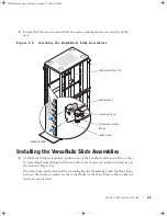
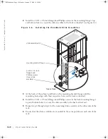
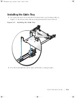
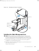
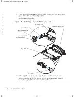
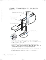
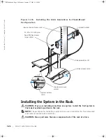
Push the tab on the remaining free end (the front) into a mating latch on the inner
segment of the slide assembly (see Figure 1-9).
The latch clicks when locked.
F i g u r e 1 - 9 .
I n s t a l l i n g t h e C a b l e - M a n a g e m e n t A r m
4
Install a stop block on the end of the opposite slide assembly (see Figure 1-9).
The stop block prevents the backward travel of the cable-management arm and
supports the weight of the arm with its load of installed cables.
latch on inner segment
of slide assembly
stop block
cable-management arm
latch on end of slide
assembly
tab on front end
tab on back end
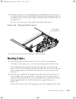
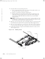
cable tray
JO525bk0.book Page 14 Monday, January 27, 2003 12:29 PM
Summary of Contents for PowerVault 725N
Page 6: ...6 Contents JO525bk0 book Page 6 Monday January 27 2003 12 29 PM ...
Page 42: ...6 Sommaire JO525fbk0 book Page 6 Monday January 27 2003 12 55 PM ...
Page 82: ...6 Inhalt JO525bk0 book Page 6 Monday January 27 2003 1 11 PM ...
Page 122: ...6 目次 JO525jbk0 book Page 6 Monday January 27 2003 3 13 PM ...
Page 160: ...6 Contenido JO525sbk0 book Page 6 Monday January 27 2003 4 29 PM ...


