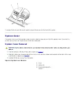
System Cover Replacement
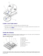
1. Ensure that tools, parts, or unconnected cables are not left inside the system.
2. Fit the cover over the sides of the chassis until the embossed rear arrowhead is aligned with the arrowhead on the
side of the cover (see
Figure 2
).
3. Slide the cover forward until the latches snap into place.
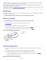
Inside the Chassis
In
Figure 3
, the system cover and bezel are removed to provide an interior view of the system. Refer to this illustration to
locate interior features and components discussed later in this manual.
Figure 3. Inside the System
1
Hard drives (4)
2
Midplane board
3
Cooling fan assembly
4
Power supply
5
Microprocessor and heat sink
6
System board
7
Memory modules (2)
8
PCI riser card
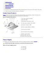
The system board holds the system's control circuitry and other electronic components. Several hardware options such as
the microprocessors and memory are installed directly on the system board. The system board can accommodate one PCI
expansion card.
Summary of Contents for PowerVault 715N
Page 10: ...Back to Contents Page ...


