background image

Installing System Components

47

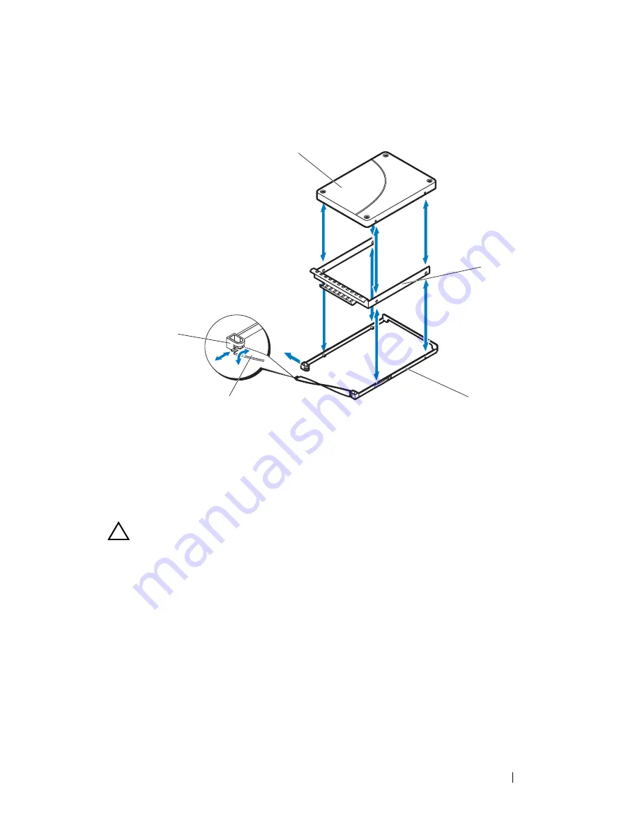
Figure 2-12. Removing and Installing a 2.5-inch SSD Hard-Drive from the SSD Hard-
Drive Carrier

Installing a 2.5-inch SSD Hard-Drive Into a SSD Hard-Drive Carrier


CAUTION: 

Many repairs may only be done by a certified service technician. You 

should only perform troubleshooting and simple repairs as authorized in your 
product documentation, or as directed by the online or telephone service and 
support team. Damage due to servicing that is not authorized is not covered by 
warranty. Read and follow the safety instructions that came with the product.

1

Insert the new SSD hard-drive into the metal shield and then align the 

holes on the hard-drive with the holes on the metal shield. Make sure that 

the metal shield with the 

arrow

 symbol is pointing up and the label on the 

drive is facing up. See Figure 2-12.

2

Lower the hard-drive assembly into the SSD hard-drive carrier. See 

Figure 2-12.

1

2.5-inch SSD hard-drive

2

metal shield 

3

SSD hard-drive carrier

4

strap handle

5

hard-drive carrier notch

2

3

4

5

1

Summary of Contents for PowerEdge C8000XD

Page 1: ...Dell PowerEdge C8000XD Hardware Owner s Manual Regulatory Model B06B Regulatory Type B06B002 ...

Page 2: ...ts reserved Reproduction of these materials in any manner whatsoever without the written permission of Dell Inc is strictly forbidden Trademarks used in this text Dell the DELL logo and PowerEdge are trademarks of Dell Inc Intel is a registered trademark of Intel Corporation in the United States or other countries Other trademarks and trade names may be used in this publication to refer to either ...

Page 3: ...9 Hard Drive Indicator Patterns 10 SAS Connectors Features 14 Expander Configuration Mode 16 Service Tag 22 Other Information You May Need 23 2 Installing System Components 25 Safety Instructions 25 Recommended Tools 26 Inside the System 27 Sled 28 Opening the Sled 28 Closing the Sled 29 Removing a Sled 30 Installing a Sled 31 ...

Page 4: ...arrier 38 Installing a Flexible Hard Drive Carrier 39 Removing a 2 5 inch Hard Drive From a Flexible Hard Drive Carrier 40 Installing a 2 5 inch Hard Drive Into a Flexible Hard Drive Carrier 41 Expansion Hard Drive Carrier 42 Removing an Expansion Hard Drive Carrier 42 Installing an Expansion Hard Drive Carrier 43 Removing a SSD Hard Drive Carrier 44 Installing a SSD Hard Drive Carrier 45 Removing...

Page 5: ...hooting a Sled 54 Troubleshooting a Hard Drive 54 Hard Drive Not Recognized 55 Hard Drive Indicator Does Not Light 55 Troubleshooting the SAS Expander Board 56 Troubleshooting the External SAS Connection 56 Troubleshooting the Hard Drive Backplane 57 Troubleshooting the Node Power Distribution Board 57 Checking the Expander Firmware Version 58 4 Using the Expander Flash Utility 59 Hardware and Sof...

Page 6: ...es 63 Expander Firmware Update Guidelines 65 Updating the Expander Firmware 65 5 Jumpers and Connectors 71 Hard Drive Backplane Connectors 71 SAS Expander Board Connectors 74 Node Power Distribution Board Connectors 75 6 Getting Help 77 Contacting Dell 77 Index 79 ...

Page 7: ...t Your System Front Panel Features and Indicators Figure 1 1 Front Panel Features and Indicators Item Indicator Button or Connector Icon Description 1 Handle Hold to pull the hard drive cage from the sled 1 2 3 4 5 6 7 8 9 10 11 ...

Page 8: ...s indicator alternately lights green and blinks amber when a critical event occurs 5 9 Sled identification indicator Lights blue to identify a particular mini SAS connector and sled 6 External mini SAS connector B2 Connects to a compute sled s host bus adapter HBA or RAID card When you configure zoning for the storage sled the external mini SAS connector becomes zone group 2 7 External mini SAS co...

Page 9: ...arrier supports 2 5 inch SAS SATA SSD hard drive Expansion hard drive carrier supports two 2 5 inch SSD hard drives The 12 drive configuration installs 12 standard or flexible hard drive carriers The 24 drive configuration installs 12 expansion hard drive carriers See Hard Drive Indicator Patterns on page 10 for information on the hard drive indicators on the sled Different patterns are displayed ...

Page 10: ... indicators alerts you to the condition of the hard drives in the sled You can view the status of the hard drive indicators on the backplane by opening the sled See Opening the Sled on page 28 The hard drive indicators are visible on both sides of the bottom edge of the hard drive cage The following illustrations show the location of the hard drive indicators in a 12 drive or 24 drive bay sled 23 ...

Page 11: ...y Hard Drive Indicators Right Side Hard Drive Cage NOTE Group A in the illustrations indicate the grouping of the hard drives in the single port mode configuration The illustration above shows the location of the hard drive indicators in a single port mode Group A Group A Group A Group A Group A Group A Group A Group A Group A Group A Group A Group A ...

Page 12: ...rives in an expansion mode zoning or non zoning configuration The illustration above shows the location of the hard drive indicators in an expansion mode In expansion mode with zoning configuration zone 0 and 1 can access grouped A hard drives and zone 2 and 3 can access group B hard drives Group B Group A Group B Group A Group B Group A Group B Group A Group B Group A Group B Group A Group B Grou...

Page 13: ...ult Indicators Green LED Green LED Amber LED Drive bay empty Off Off Off Drive idle Off Off Off Drive online access On 50 ms Off 50 ms On Off Drive identify Preparing for removal On 100 ms Off 100 ms On 250 ms Off 250 ms Off Drive rebuilding On 500 ms Off 500 ms On 400 ms Off 100 ms Off Drive failed Off Blinking when active Off On 150 ms Off 150 ms Predicted drive failure SMART Off Blinking when a...

Page 14: ... mini SAS connectors support hard drive backplane connection the hard drives and SAS expander in the storage sled communicates via the hard drive backplane The storage sled includes an Expander Flash Utility Xflash This utility is a Windows or Linux based command line utility that you can use to identify the SAS address of the SAS expander determine the expander firmware version reset the SAS expa...

Page 15: ...About Your System 15 Figure 1 8 SAS Expander Board SAS Expander Board ...

Page 16: ...ation modes Single port mode In single port mode the storage sled supports 12 x 2 5 or 3 5 inch SAS SATA SSD hard drives from a single cable connection The figure below shows a single path connection from a single HBA RAID compute sled to the storage sled s external mini SAS A1 and A2 connectors In this mode the hard drives in the storage sled are cascaded for extended storage capacity Figure 1 9 ...

Page 17: ... single HBA RAID compute sled to two cascaded storage sleds In this mode the hard drives in the two storage sleds are cascaded for extended storage capacity Figure 1 10 Single Host to Cascaded Storage Sled Connection Single HBA RAID Compute Sled Storage Sled 2 Storage Sled 1 ...

Page 18: ...drives from a dual cable connection The figure below shows a dual path connection from a dual HBA compute sled connected to the storage sled s external mini SAS A1 and B1 connectors This mode delivers dual path functionality and redundant path capability Figure 1 11 Dual Port Mode Configuration Dual HBA Compute Sled Storage Sled ...

Page 19: ... a dual cable connection The figure below shows a dual path connection from a single RAID compute sled connected to the storage sled s external mini SAS A1 and A2 connectors In this mode the hard drives in the storage sled are cascaded for extended storage capacity Figure 1 12 Expansion Mode Non Zoning Single RAID Compute Sled Storage Sled ...

Page 20: ...1 Zone 2 B2 Zone 3 and each zone allows the host compute sled to access a group of hard drives in the storage sled The figure below shows four single RAID compute sleds connected to the storage sled s four external mini SAS connectors Each compute sled can only access the hard drives in the assigned zone Figure 1 13 Expansion Mode Four Zones Figure 1 14 Zoning Table Single RAID Compute Sleds Stora...

Page 21: ...1 Zone 0 and A2 Zone 1 and each zone allows the host compute sled to access a group of hard drives in the storage sled The figure below shows two single RAID compute sleds connected to the storage sled s external mini SAS A1 and A2 connectors Each compute sled can only access the hard drives in the assigned zone Figure 1 15 Expansion Mode Two Zones Figure 1 16 Zoning Table Single HBA RAID Compute ...

Page 22: ...22 About Your System Service Tag The following illustration provides location of the Service Tag number on the C8000XD storage sled Figure 1 17 Service Tag Location for C8000XD Storage Sled ...

Page 23: ...s Manual for information about the server enclosure features troubleshooting and component replacement This document is available at support dell com manuals The compute sleds documentation provides information about the sled features configuring and managing the sled This document is available at support dell com manuals The Baseboard Management Controller Guide provides information about install...

Page 24: ...24 About Your System ...

Page 25: ... is not covered by your warranty Read and follow the safety instructions that came with the product To avoid injury to yourself or damage to your system follow these guidelines Always disconnect the system from the power outlet whenever you are working inside the system If possible wear a grounded wrist strap when you are working inside the system Alternatively discharge any static electricity by ...

Page 26: ...m evenly aligned to avoid bending any connector pins Also before you connect a cable ensure that both connectors are correctly oriented and aligned About the Illustrations The illustrations used in this chapter identifies the component parts and does not show step by step component removal or replacement instructions Recommended Tools 1 Phillips screwdriver 2 Phillips screwdriver Torx drivers Set ...

Page 27: ...authorized in your product documentation or as directed by the online or telephone service and support team Damage due to servicing that is not authorized is not covered by warranty Read and follow the safety instructions that came with the product Figure 2 1 Inside the C8000XD 1 hard drive bays 2 hard drive cage 3 SAS expander board 4 mini SAS cables 5 hard drive backplane 1 2 3 4 5 ...

Page 28: ...by the online or telephone service and support team Damage due to servicing that is not authorized is not covered by warranty Read and follow the safety instructions that came with the product 1 Press and hold the hard drive cage release latch See Figure 2 2 2 Using the handle slide the hard drive cage out until the inner rails lock into place See Figure 2 2 Figure 2 2 Opening and Closing the Sled...

Page 29: ...lace See Figure 2 2 2 If you pulled the hard drive cage to the fully extended position slide the rail release latches on each side of the hard drive cage and push the hard drive cage into the sled until it locks into place See Figure 2 3 Figure 2 3 Closing the Fully Extended Hard Drive Cage 1 rail release latches 2 2 hard drive cage 3 storage sled 1 2 3 ...

Page 30: ...that came with the product CAUTION To ensure proper airflow in the system if a module is removed it should be immediately replaced with another sled or sled blank CAUTION Operating the system without a sled or sled blank installed can cause the PowerEdge C8000 server enclosure to overheat See Installing a Sled Blank on page 32 1 Pull and hold the storage sled release tab at the bottom of the sled ...

Page 31: ...ctions that came with the product 1 Orient the sled so that the release latch is in the left of the sled See Figure 2 4 2 Slide the new sled into the server enclosure until the sled is fully seated and the sled release tab snaps into place See Figure 2 4 Sled Blank Removing a Sled Blank CAUTION To ensure proper airflow in the system if a module is removed it should be immediately replaced with ano...

Page 32: ...ble hard drive carrier Expansion hard drive carrier Hard Drive Configuration The sled is equipped with a SAS expander to operate the drives in single port dual port or expansion mode In single port mode the SAS expander board supports 12 x 2 5 or 3 5 inch SAS SATA SSD hard drives from a single cable connection In dual port mode the SAS expander board supports 12 x 2 5 or 3 5 inch SAS hard drives f...

Page 33: ... standard or flexible carriers is not supported The sled only supports SAS hard drives in dual port mode configuration Use only SSD hard drives when configuring the SAS expander in expansion mode configuration Table 2 1 Hard Drive Configuration Expander Configuration Mode Hard Drive Carrier Type Drive Size Drive Type and Height Total Drive Capacity SAS SATA SSD Mode 1 Single Port Mode Standard 3 5...

Page 34: ...ot covered by warranty Read and follow the safety instructions that came with the product CAUTION To maintain proper system cooling all empty hard drive slots must have hard drive blanks installed CAUTION Use only hard drives that have been tested and approved for use with the hard drive backplane CAUTION To prevent data loss ensure that your operating system supports hot swappable drive installat...

Page 35: ...ce and support team Damage due to servicing that is not authorized is not covered by warranty Read and follow the safety instructions that came with the product NOTE Orient the standard hard drive carrier so that the carrier s strap handle is flush against the wall of the hard drive cage See Figure 2 6 1 Align the standard hard drive carrier to the drive bay and then slide the hard drive carrier i...

Page 36: ...mpty hard drive slots must have hard drive blanks installed CAUTION Use only hard drives that have been tested and approved for use with the hard drive backplane CAUTION To prevent data loss ensure that your operating system supports hot swappable drive installation See the documentation supplied with the operating system NOTE Only SAS hard drives are supported in a dual cable SAS expander connect...

Page 37: ...ce and support team Damage due to servicing that is not authorized is not covered by warranty Read and follow the safety instructions that came with the product 1 Insert the new hard drive into the metal shield and then align the holes on the hard drive with the holes on the metal shield Make sure that the metal shield with the arrow symbol is pointing up and the label on the drive is facing up Se...

Page 38: ... repairs as authorized in your product documentation or as directed by the online or telephone service and support team Damage due to servicing that is not authorized is not covered by warranty Read and follow the safety instructions that came with the product CAUTION To maintain proper system cooling all empty hard drive slots must have hard drive blanks installed CAUTION Use only hard drives tha...

Page 39: ...ce and support team Damage due to servicing that is not authorized is not covered by warranty Read and follow the safety instructions that came with the product NOTE Orient the flexible hard drive carrier so that the carrier s strap handle is flush against the wall of the hard drive cage See Figure 2 8 1 Align the flexible hard drive carrier to the drive bay and then slide the hard drive carrier i...

Page 40: ...nks installed CAUTION Use only hard drives that have been tested and approved for use with the hard drive backplane CAUTION To prevent data loss ensure that your operating system supports hot swappable drive installation See the documentation supplied with the operating system NOTE Only SAS hard drives are supported in a dual cable SAS expander connection 1 Rotate the strap handle to unlock it fro...

Page 41: ... instructions that came with the product 1 Lower the hard drive into the flexible hard drive carrier See Figure 2 9 2 Flex the back right side rail and insert the carrier pins into the hard drive mounting holes and then flex the left side rail and insert the pins into the other mounting holes See Figure 2 9 3 Flex the front right side rail and insert the carrier pins into the metal shield mounting...

Page 42: ...roduct documentation or as directed by the online or telephone service and support team Damage due to servicing that is not authorized is not covered by warranty Read and follow the safety instructions that came with the product CAUTION To maintain proper system cooling all empty hard drive slots must have hard drive blanks installed CAUTION Use only hard drives that have been tested and approved ...

Page 43: ...pport team Damage due to servicing that is not authorized is not covered by warranty Read and follow the safety instructions that came with the product NOTE Orient the expansion hard drive carrier so that the carrier s strap handle and drive carrier is flush against the wall of the hard drive cage See Figure 2 10 1 Align the expansion hard drive carrier to the drive bay and then slide the hard dri...

Page 44: ...ling all empty hard drive slots must have hard drive blanks installed CAUTION Use only hard drives that have been tested and approved for use with the hard drive backplane CAUTION To prevent data loss ensure that your operating system supports hot swappable drive installation See the documentation supplied with the operating system NOTE Only SAS hard drives are supported in a dual cable SAS expand...

Page 45: ...me with the product NOTE Orient the SSD hard drive carrier so that the carrier s strap handle is flush against the wall of the hard drive cage See Figure 2 11 1 Rotate the expansion hard drive carrier s strap handle to unlock it from the hard drive carrier See Figure 2 11 2 Slide the SSD hard drive carrier into the expansion hard drive carrier until the SSD hard drive is fully seated 3 Fit the t s...

Page 46: ...rive slots must have hard drive blanks installed CAUTION Use only hard drives that have been tested and approved for use with the hard drive backplane CAUTION To prevent data loss ensure that your operating system supports hot swappable drive installation See the documentation supplied with the operating system NOTE Only SAS hard drives are supported in a dual cable SAS expander connection 1 Rotat...

Page 47: ...ice and support team Damage due to servicing that is not authorized is not covered by warranty Read and follow the safety instructions that came with the product 1 Insert the new SSD hard drive into the metal shield and then align the holes on the hard drive with the holes on the metal shield Make sure that the metal shield with the arrow symbol is pointing up and the label on the drive is facing ...

Page 48: ...and support team Damage due to servicing that is not authorized is not covered by warranty Read and follow the safety instructions that came with the product CAUTION To maintain proper system cooling all empty hard drive slots must have hard drive blanks installed CAUTION Use only hard drives that have been tested and approved for use with the hard drive backplane CAUTION To prevent data loss ensu...

Page 49: ...mage due to servicing that is not authorized is not covered by warranty Read and follow the safety instructions that came with the product NOTE Orient the SSD hard drive carrier so that the hard drive connector aligns with the interface connector on the expansion hard drive carrier 1 Slide the SSD hard drive carrier into the expansion hard drive carrier until the SSD hard drive is fully seated See...

Page 50: ...d in the expansion hard drive carrier to maintain proper airflow even when the hard drive carrier or sled is in a diskless configuration 1 Remove the expansion hard drive carrier from the sled See Removing an Expansion Hard Drive Carrier on page 42 2 Remove the SSD hard drives from the expansion hard drive carrier See Removing a SSD Hard Drive Carrier From an Expansion Hard Drive Carrier on page 4...

Page 51: ...oduct documentation or as directed by the online or telephone service and support team Damage due to servicing that is not authorized is not covered by warranty Read and follow the safety instructions that came with the product 1 Align the hard drive backplane with the screw holes on the hard drive tray See Figure 2 14 2 Replace the three screws securing the hard drive backplane to the hard drive ...

Page 52: ...es and then flex the left side rail and insert the carrier pins into the other mounting holes See Figure 2 14 4 Install the SSD hard drives See Installing a SSD Hard Drive Carrier Into an Expansion Hard Drive Carrier on page 49 5 Fit the t shaped end of the expansion hard drive carrier strap handle into the notch and then twist to lock the strap handle ...

Page 53: ... team Damage due to servicing that is not authorized by Dell is not covered by your warranty Read and follow the safety instructions that came with the product Installation Problems Perform the following checks if you are troubleshooting an installation problem Check all cable and power connections including all rack cable connections Unplug the power cord and wait for one minute Then reconnect th...

Page 54: ...y Read and follow the safety instructions that came with the product 1 Ensure all cables are properly connected to the server enclosure 2 Ensure that the sled is fully seated See Closing the Sled on page 29 3 Ensure that the sled are properly installed 4 Ensure that all components are properly installed and free of damage See Installing System Components on page 25 5 If the sled fails to power up ...

Page 55: ...lexible Hard Drive Carrier on page 39 or Installing an Expansion Hard Drive Carrier on page 43 7 Close the sled See Closing the Sled on page 29 8 If the problem persists install a new hard drive Hard Drive Indicator Does Not Light 1 Open the sled See Opening the Sled on page 28 NOTE You must ensure that you check the hard drive indicators before removing the faulty hard drive from the sled 2 Locat...

Page 56: ... pins for damage 3 Ensure that the SAS expander board is installed properly in the sled 4 Reinstall the sled into the enclosure See Installing a Sled on page 31 If the problem persists see Getting Help on page 77 Troubleshooting the External SAS Connection CAUTION Many repairs may only be done by a certified service technician You should only perform troubleshooting and simple repairs as authorize...

Page 57: ... the sled from the server enclosure See Removing a Sled on page 30 2 Ensure that the cables are firmly seated in their connectors in the hard drive backplane Or check the connector pins for damage 3 Ensure that the hard drive backplane is installed properly in the sled 4 Reinstall the sled into the enclosure See Installing a Sled on page 31 If the problem persists see Getting Help on page 77 Troub...

Page 58: ...t avail where i selects the interface is the inband SAS address get queries data from the targeted expander chip avail lists expanders available to the selected interface 3 Check the expander chip firmware version Enter the following command line to view the expander chip firmware version cmd xflash i SASADDR get ver 0 where i selects the interface is the inband SAS address SASADDR is the inband S...

Page 59: ...rately Hardware and Software Requirements Xflash runs on the following platforms Double wide or single wide compute sled with HBA or RAID card mini SAS x4 cable SFF 8088 cables Windows Server 2012 Standard x64 Windows Server 2008 R2 Enterprise x64 Red Hat Enterprise Linux RHEL 6 1 x64 SUSE Linux Enterprise Server SLES 11 2 GM x64 SAS Expander Support Xflash supports the following SAS expander chip...

Page 60: ...s Parameter Description h help Display command line options help information l log Create a log file for internal operations r resetchip Hard reset the expander chip A or B after current command completion Table 4 2 INTERFACE Command Line Parameters Parameter Description i SAS ADDRESS inband SAS ADDRESS Utilize inband port SAS ADDRESS to connect to the expander NOTE Use the command get avail when ...

Page 61: ...cription down Download a firmware or manufacturing image to the expander fw FILE REGION a Download a new firmware image to the expander chip mfg FILE REGION a Download a new manufacturing image to the expander chip s manufacturing region erase Erase regions of flash on the expander chip flash Erase the entire flash fw REGION b Erase a firmware region mfg REGION b Erase the expander chip s flash ma...

Page 62: ...rive sled In this configuration the host is connected to the storage sled s external mini SAS A1 and mini SAS B1 connectors and the 12 hard drives are unified and controlled by expander chips A and B See Figure 1 11 This cabling option supports HBA cards only and allows you to manually update the expander firmware on both expander chips one at a time You will need to switch the cables in the mini ...

Page 63: ...he two hosts are connected to the storage sled and the 12 hard drives are grouped into two zones Expander chip A controls zones 0 and 1 See Figure 1 15 This cabling option supports both HBA and RAID cards and allows you to manually update the expander firmware on both expander chips one at a time You will need to switch the cables in the mini SAS A1 and mini SAS B1 connectors to update the second ...

Page 64: ...2xfwZeus_XXX fw 2 4 Expander A B sas2xfwZeus_XXX fw 2 5 Expander A B sas2xfwZeus_XXX fw 2 Table 4 6 Region 3 Expander Manufacturing File Names Configuration Type Manufacturing Image File Name Region 1 Expander A B sas2xMfgZeus_XXX bin 3 2 Expander A B sas2xMfgZeus_XXX bin 3 3 Expander A B sas2xMfgZeus_XXX bin 3 4 Expander A B sas2xMfgZeus_XXX bin 3 5 Expander A B sas2xMfgZeus_XXX bin 3 Table 4 7 R...

Page 65: ...pdate operation has completed Updating the Expander Firmware NOTE Before performing the firmware update make sure to download the latest firmware version and save it on your local system During the process of an expander firmware update the C8000XD sled must not be removed from the C8000 server enclosure CAUTION Do not erase the expander firmware flash image when the firmware update is in progress...

Page 66: ...e is correct See Expander Firmware File Names on page 63 5 Take note of the expander chips A and B SAS addresses 6 Update the expander firmware on the expander chips 7 Download the expander firmware to flash region 0 a Enter the following command cmd xflash i SASADDR down fw sas2xfwZeus_XXX fw 0 where SASADDR is the inband SAS address of the specified expander chip XXX is the firmware image versio...

Page 67: ...ber For example the command line should have the following format cmd xflash i 500650b0000472bf down fw sas2xfwZeus_120518_1_0_2_0 fw 2 b When the Are you sure to download file to expander y n message prompt appears press Y 9 Download the manufacturing image to flash region 3 a Enter the following command cmd xflash i SASADDR down mfg sas2xMfgZeus_XXX bin 3 where SASADDR is the inband SAS address ...

Page 68: ...ars press Y 11 Wait until the download in region 9 completes and the Post validation of image is successful message appears on the screen 12 If you are updating the expander firmware using configuration 1 or 3 cabling option proceed to step 13 If you are updating the expander firmware using configuration 2 or 4 cabling option you need to switch the mini SAS cables on the storage sled and repeat st...

Page 69: ...rmware version by entering the command cmd xflash i SASADDR get ver 0 16 Check the region 2 firmware version by entering the command cmd xflash i SASADDR get ver 2 17 Check the region 3 manufacturing version by entering the command cmd xflash i SASADDR get ver 3 ...

Page 70: ...70 Using the Expander Flash Utility ...

Page 71: ... Hard Drive Backplane Connectors Figure 5 1 Left Hard Drive Backplane 1 onboard SAS SATA connector 0 or 12 2 onboard SAS SATA connector 2 or 14 3 backplane bridge board connector 4 onboard SAS SATA connector 3 or 15 5 onboard SAS SATA connector 1 or 13 ...

Page 72: ...nnector 8 or 20 6 onboard SAS SATA connector 10 or 22 7 mini SAS connector 0 8 mini SAS connector 1 9 expander I2C connector 10 mini SAS connector 2 11 mini SAS connector 3 12 onboard SAS SATA connector 11 or 23 13 onboard SAS SATA connector 9 or 21 14 onboard SAS SATA connector 7 or 19 15 onboard SAS SATA connector 5 or 17 16 onboard SAS SATA connector 4 or 16 1 2 3 4 5 10 11 12 13 14 15 6 7 8 9 ...

Page 73: ...Jumpers and Connectors 73 Figure 5 3 Expansion Hard Drive Carrier Hard Drive Backplane 1 onboard SSD connector 1 2 onboard SSD connector 2 ...

Page 74: ...ector for controller 2 3 internal mini SAS connector 3 4 internal mini SAS connector 2 5 internal mini SAS connector 1 6 internal mini SAS connector 0 7 power connector 8 expander I2C connector 1 9 smart debug connector for controller 1 10 RS232 COM connector 11 controller select jumper 12 expander I2C connector 2 13 external mini SAS connectors B1 and B2 ...

Page 75: ...y throttling connector 2 I2C connector 3 12 V S2 power connector 4 HDD1 power connector 5 power connector 6 HDD3 power connector 7 HDD2 power connector 8 system board power connector 9 12 V S1 power connector 10 remote sensor connector 11 hard drive LED indicator connector 12 system board control connector 13 LAN pass through connector ...

Page 76: ...76 Jumpers and Connectors ...

Page 77: ...ephone based support and service options Availability varies by country and product and some services may not be available in your area To contact Dell for sales technical support or customer service issues 1 Visit support dell com 2 Click your country region at the bottom of the page For a full listing of country region click All 3 Click All Support from Support menu 4 Select the appropriate serv...

Page 78: ...78 Getting Help ...

Page 79: ...8 removing 36 A about your system 7 C closing sled 29 D Dell contacting 77 E expander configuration mode 16 expander firmware updating 65 expander firmware update guidelines 65 Expander Flash Utility 59 cabling configurations 62 command description 60 firmware update 65 requirements 59 expansion carrier backplane installing 51 removing 50 expansion hard drive carrier installing 43 removing 42 F fe...

Page 80: ... sled blank 32 SSD hard drive carrier 45 49 standard hard drive carrier 35 O opening sled 28 R removing 2 5 inch hard drive 40 2 5 inch SSD hard drive 46 3 5 inch hard drive 36 expansion carrier backplane 50 expansion hard drive carrier 42 flexible hard drive carrier 38 39 sled 30 sled blank 31 SSD hard drive carrier 44 48 standard hard drive carrier 34 35 S safety 53 service tag 22 sled closing 2...

Page 81: ...M Hardware Owners Manual DWS Sled C8000XD C8000XD_HOM_bk0IX fm Index 81 T troubleshooting expander board 56 expander connectors 56 external connections 54 firmware version 58 hard drive 54 hard drive backplane 57 NPDB 57 X Xflash See Expander Flash Utility ...

Page 82: ...FILE LOCATION D Projects User Guide Server Dell OOB HOM Hardware Owners Manual DWS Sled C8000XD C8000XD_HOM_bk0IX fm 82 Index ...

Reviews: