- 11 -
5. Disassembly and Assembly Procedures
NOTE
:
This “Disassembly and Assembly Procedures” is for EMEA only, not for other regions. Please note
that Dell will deem warranty void if any disassembly is done on the monitors.
5.1 Disassembly SOP
Preparation before disassembly
1. Clean the room for work
2. Identify the area for material
3. Prepare the implement, equipment, materials as bellow
:
1) Working table
2) Philips-head screwdriver
3) Gloves
4) Cleaning cloth
5) ESD protection
6) Bar Scraper
7) U3415W curve sponge jig
Item
Picture
Operation
Tool
Notes
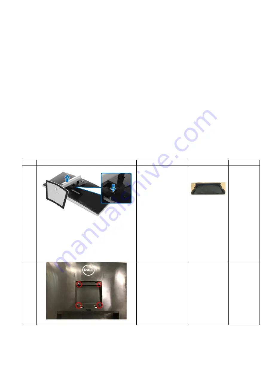
1
To remove the stand:
1. Place the monitor
on U3415W curve
sponge jig
2. Press and hold
the stand release
button
3. Lift the stand up
and away from the
monitor
U3415W curve
sponge jig
Panel and
whole
monitor head
must be put
on U3415W
curve sponge
jig to avoid
panel
damage.
It is not
allowed to
place the
front side of
panel and
monitor head
on a flat
surface
2
1. Unlock 4 screws
on rear cover
Philips-head
screwdriver
Torsion of RC
screw: 11±1Kg
Summary of Contents for P3421WB
Page 1: ... 1 Service Manual P3421WB Version 01 Date 2021 10 08 ...
Page 6: ... 6 2 Exploded view diagram with list of items 22 23 24 25 26 ...
Page 8: ... 8 3 Wiring connectivity diagram Wire1 FFC 1 FFC 2 Wire2 Wire3 Wire4 ...
Page 18: ... 18 6 Trouble shooting instructions ...
Page 19: ... 19 ...
Page 20: ... 20 ...
Page 21: ... 21 ...
Page 22: ... 22 ...
Page 23: ... 23 ...
Page 24: ... 24 ...
Page 25: ... 25 ...
Page 26: ... 26 ...


