4. Disassembly and Assembly Procedures
4
.2 Assembly Procedures:
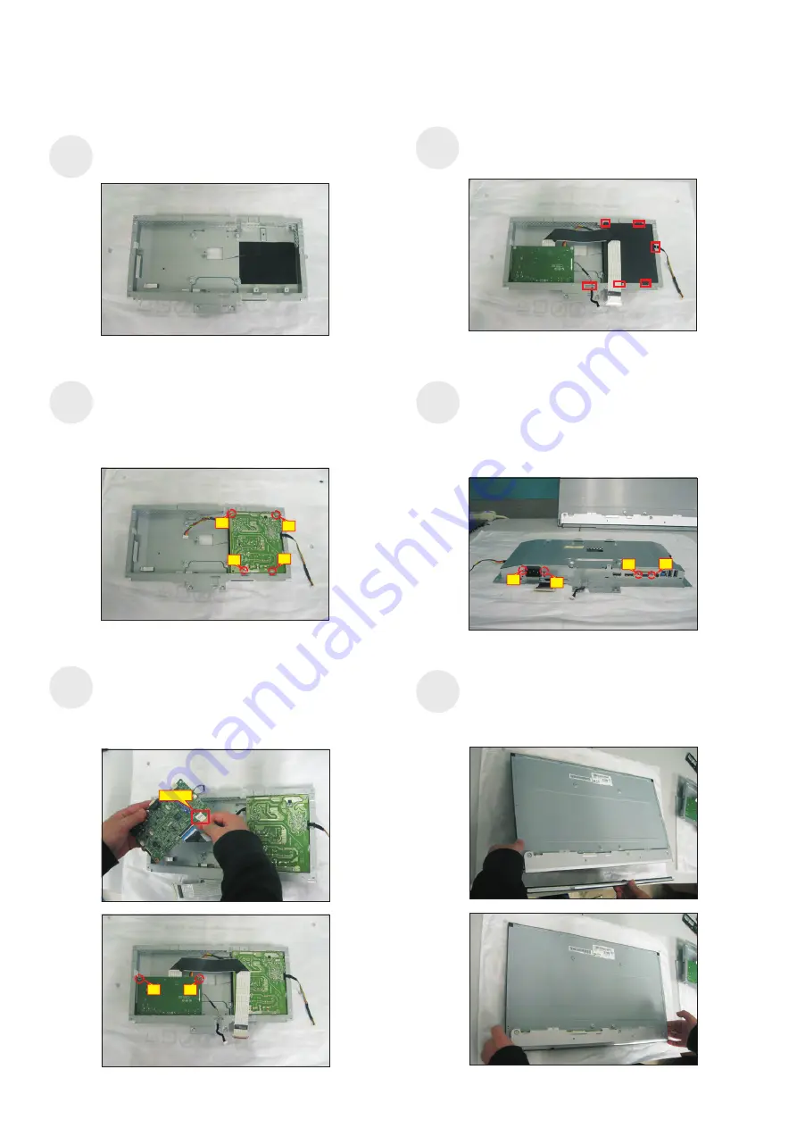
Turn over a power board and put the power board
into the bracket chassis, then use a Philips-head
screwdriver to tighten four screws for locking the
power board.
(No.1 screw size=M4x8, Torque=6
±0.5
kgfxcm;
No.2~4 screw size=M3x7.5, Torque=6
±0.5
kgfxcm)
Place a bracket chassis base on a protective
cushion.
S2
S1
Take a mylar to insert the hooks of the bracket to
cover the power board. locate the two cables into the
hook of the bracket chassis.
S4
Take a interface board, connect the cable of the
power board to the CN2201 of the interface board.
Turn over the interface board and locate it into the
bracket. Use a Philips-head screwdriver to tighten
two screws for locking the interface board.
(No.1~2 screw size=M3x7.5, Torque=6
±0.5
kgfxcm)
2
1
CN2201
S3
4
2
3
1
Panel preparation: Examine the panel surface
according to inspection criteria. Turn over the panel
to place screen faced down. Take a front bezel and
put the front bezel under the panel as the below
picture shown.
S6
Turn over the bracket chassis module and then
Philips-head screwdriver to tighten
use
a
two screws for
locking the AC-power outlet connector. And Use a
Hex-head screwdriver to tighten two screws for
locking mechanisms of the VGA connectors.
(No.1~2 screw size=M3x10, Torque=6
±0.5
kgfxcm)
(No.3~4 screw size=M3x8, Torque=6
±0.5
kgfxcm)
S5
2
3
4
1


