vii
Figure 1-4.
Riser Board . . . . . . . . . . . . . . . . . . . . . . . . . . . . . . . . . . . . . . . 1-4
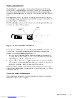
Figure 1-5.
NIC Connector on I/O Panel . . . . . . . . . . . . . . . . . . . . . . . . . . 1-5
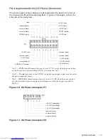
Figure 1-6.
DC Power Connector P1 . . . . . . . . . . . . . . . . . . . . . . . . . . . . . 1-7
Figure 1-7.
DC Power Connector P2 . . . . . . . . . . . . . . . . . . . . . . . . . . . . . 1-7
Figure 1-8.
DC Power Connector P3 . . . . . . . . . . . . . . . . . . . . . . . . . . . . . 1-8
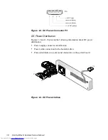
Figure 1-9.
DC Power Cables . . . . . . . . . . . . . . . . . . . . . . . . . . . . . . . . . . . 1-8
Figure 1-10. DC Power Distribution. . . . . . . . . . . . . . . . . . . . . . . . . . . . . . . 1-9
Figure 1-11. System Board Components . . . . . . . . . . . . . . . . . . . . . . . . . . 1-10
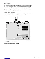
Figure 1-12. System Board Jumpers. . . . . . . . . . . . . . . . . . . . . . . . . . . . . . 1-11
Figure 2-1.
External Diskette Drive . . . . . . . . . . . . . . . . . . . . . . . . . . . . . . 2-8
Figure 4-1.
Optional Stand Removal . . . . . . . . . . . . . . . . . . . . . . . . . . . . . 4-3
Figure 4-2.
Computer Cover Removal . . . . . . . . . . . . . . . . . . . . . . . . . . . . 4-4
Figure 4-3.
Service Access Lock . . . . . . . . . . . . . . . . . . . . . . . . . . . . . . . . 4-4
Figure 4-4.
Control Panel Removal . . . . . . . . . . . . . . . . . . . . . . . . . . . . . . 4-6
Figure 4-5.
Hard-Disk Drive Removal . . . . . . . . . . . . . . . . . . . . . . . . . . . . 4-7
Figure 4-6.
System Power-Supply Removal. . . . . . . . . . . . . . . . . . . . . . . . 4-8
Figure 4-7.
System Board Components . . . . . . . . . . . . . . . . . . . . . . . . . . . 4-9
Figure 4-8.
Expansion-Card Cage Removal . . . . . . . . . . . . . . . . . . . . . . . 4-10
Figure 4-9.
Expansion-Card Removal . . . . . . . . . . . . . . . . . . . . . . . . . . . 4-11
Figure 4-10. Riser Board Removal . . . . . . . . . . . . . . . . . . . . . . . . . . . . . . . 4-12
Figure 4-11. DIMM Removal . . . . . . . . . . . . . . . . . . . . . . . . . . . . . . . . . . . 4-13
Figure 4-12. DIMM Installation . . . . . . . . . . . . . . . . . . . . . . . . . . . . . . . . . 4-13
Figure 4-13. Microprocessor Removal . . . . . . . . . . . . . . . . . . . . . . . . . . . . 4-14
Figure 4-14. Microprocessor Securing-Clip Removal . . . . . . . . . . . . . . . . 4-15
Figure 4-15. System Battery Removal . . . . . . . . . . . . . . . . . . . . . . . . . . . . 4-16
Figure 4-16. System Board Removal . . . . . . . . . . . . . . . . . . . . . . . . . . . . . 4-17
Figure A-1.
System Setup Screens . . . . . . . . . . . . . . . . . . . . . . . . . . . . . . .A-2
Figure A-2.
Sample Device List Screen . . . . . . . . . . . . . . . . . . . . . . . . . . .A-6
Tables
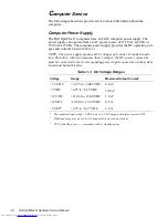
Table 1-1.
DC Voltage Ranges . . . . . . . . . . . . . . . . . . . . . . . . . . . . . . . . . 1-6
Table 1-2.
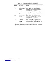
System-Board Jumper Descriptions. . . . . . . . . . . . . . . . . . . . 1-12
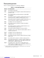
Table 1-3.
Interrupt Assignments . . . . . . . . . . . . . . . . . . . . . . . . . . . . . . 1-13
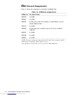
Table 1-4.
DREQ Line Assignments. . . . . . . . . . . . . . . . . . . . . . . . . . . . 1-14
Table 1-5.
Technical Specifications . . . . . . . . . . . . . . . . . . . . . . . . . . . . 1-15
Table 3-1.
POST Beep Codes . . . . . . . . . . . . . . . . . . . . . . . . . . . . . . . . . . 3-2
Table 3-2.
System Error Messages . . . . . . . . . . . . . . . . . . . . . . . . . . . . . . 3-5
Table A-1.
System Setup Categories . . . . . . . . . . . . . . . . . . . . . . . . . . . . .A-3

