background image

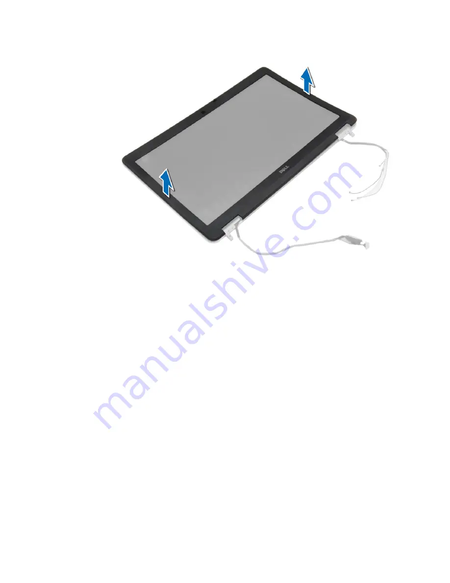
Installing the Display Bezel

1.

Place the display bezel onto the display assembly.

2.

Starting from the top corner, press on the display bezel and work around the entire bezel until it clicks onto the 

display assembly.

3.

Press on the left and right edges of the display bezel.

4.

Install:
a) display assembly
b) base corner caps
c) base cover
d) display-hinge cap
e) battery

5.

Follow the procedures in 

After Working Inside Your Computer

.

Removing the Display Panel

1.

Follow the procedures in 

Before Working Inside Your Computer

.

2.

Remove:
a) battery
b) display-hinge cap
c) base cover
d) base corner caps
e) display assembly
f) display bezel

49

Summary of Contents for Latitude E6540

Page 1: ...Dell Latitude E6540 Owner s Manual Regulatory Model P29F Regulatory Type P29F001 ...

Page 2: ... Sempron are trademarks of Advanced Micro Devices Inc Microsoft Windows Windows Server Internet Explorer MS DOS Windows Vista and Active Directory are either trademarks or registered trademarks of Microsoft Corporation in the United States and or other countries Red Hat and Red Hat Enterprise Linux are registered trademarks of Red Hat Inc in the United States and or other countries Novell and SUSE...

Page 3: ...7 Installing the Base Corner Caps 18 Removing the Memory 18 Installing the Memory 19 Removing the Hard Drive 19 Installing the Hard Drive 20 Removing the Optical Drive 20 Installing the Optical Drive 21 Removing the Wireless Local Area Network WLAN Card 22 Installing the WLAN Card 22 Removing the Wireless Wide Area Network WWAN Card 22 Installing the WWAN Card 23 Removing the Network Connector 23 ...

Page 4: ...Removing the Display Assembly 43 Installing the Display Assembly 47 Removing the Display Bezel 47 Installing the Display Bezel 49 Removing the Display Panel 49 Installing the Display Panel 51 Removing the Display Hinges 51 Installing the Display Hinges 52 Removing the Camera 52 Installing the Camera 53 3 System Setup 55 Boot Sequence 55 Navigation Keys 55 System Setup Options 56 Updating the BIOS ...

Page 5: ...6 Contacting Dell 75 ...

Page 6: ...6 ...

Page 7: ...ching an unpainted metal surface such as a connector on the back of the computer CAUTION Handle components and cards with care Do not touch the components or contacts on a card Hold a card by its edges or by its metal mounting bracket Hold a component such as a processor by its edges not by its pins CAUTION When you disconnect a cable pull on its connector or on its pull tab not on the cable itsel...

Page 8: ... installed ExpressCards or Smart Cards from the appropriate slots Turning Off Your Computer CAUTION To avoid losing data save and close all open files and exit all open programs before you turn off your computer 1 Shut down the operating system In Windows 8 Using a touch enabled device a Swipe in from the right edge of the screen opening the Charms menu and select Settings b Select the and then se...

Page 9: ...ot use batteries designed for other Dell computers 1 Connect any external devices such as a port replicator battery slice or media base and replace any cards such as an ExpressCard 2 Connect any telephone or network cables to your computer CAUTION To connect a network cable first plug the cable into the network device and then plug it into the computer 3 Replace the battery 4 Connect your computer...

Page 10: ...10 ...

Page 11: ...nts from your computer Recommended Tools The procedures in this document may require the following tools Small flat blade screwdriver Phillips screwdriver Small plastic scribe System Overview Figure 1 Back View Back Cover Removed 1 heat sink assembly 2 hard drive 3 memory 4 SD card 5 ExpressCard slot 6 optical drive 11 ...

Page 12: ...almrest Assembly removed 1 WiFi switch board 2 speaker 3 ExpressCard cage 4 system board 5 speaker 6 hard drive bay 7 VGA board 8 display assembly Removing the Secure Digital SD Card 1 Follow the procedures in Before Working Inside Your Computer 2 Press in on the SD card to release it from the computer Slide the SD card out of the computer 12 ...

Page 13: ... Working Inside Your Computer 2 Press in on the ExpressCard to release it from the computer Slide the ExpressCard out of the computer Installing the ExpressCard 1 Slide the ExpressCard in its slot until it clicks in place 2 Follow the procedures in After Working Inside Your Computer Removing the Battery 1 Follow the procedures in Before Working Inside Your Computer 2 Slide the release latches to u...

Page 14: ...3 Flip the battery out of the computer 14 ...

Page 15: ...its slot until it clicks into place 2 Follow the procedures in After Working Inside Your Computer Removing the Base Cover 1 Follow the procedures in Before Working Inside Your Computer 2 Remove the screws that secure the base cover to the computer 15 ...

Page 16: ...3 Lift the base cover and remove it from the computer 16 ...

Page 17: ...ver to the computer 3 Install the battery 4 Follow the procedures in After Working Inside Your Computer Removing the Base Corner Caps 1 Follow the procedures in Before Working Inside Your Computer 2 Remove the battery 3 Remove the base cover 4 Remove the screws that secure the left base corner cap lift and remove it from the computer 17 ...

Page 18: ...right base corner caps to align with the screw holes on the computer 2 Tighten the screws to secure the base corner caps to the computer 3 Install a base cover b battery 4 Follow the procedures in After Working Inside Your Computer Removing the Memory 1 Follow the procedures in Before Working Inside Your Computer 2 Remove a battery b base cover 18 ...

Page 19: ...odule to the system board 3 Install a base cover b battery 4 Follow the procedures in After Working Inside Your Computer Removing the Hard Drive 1 Follow the procedures in Before Working Inside Your Computer 2 Remove the battery 3 Remove the screws that secure the hard drive to the computer Slide the hard drive out of the computer 4 Remove the screw that secures the hard drive caddy to the hard dr...

Page 20: ...the hard drive caddy to the hard drive 4 Slide the hard drive into the computer 5 Tighten the screws to secure the hard drive to the computer 6 Install the battery 7 Follow the procedures in After Working Inside Your Computer Removing the Optical Drive 1 Follow the procedures in Before Working Inside Your Computer 2 Remove the battery 3 Press the optical drive latch to release the optical drive an...

Page 21: ...e the latch bracket from the optical drive Installing the Optical Drive 1 Align the optical drive latch bracket to its position on the optical drive 2 Tighten the screw to secure the optical drive latch bracket to the optical drive 3 Slide the optical drive latch in the optical drive latch bracket 4 Tighten the screws to secure the optical drive latch to the optical drive latch bracket 5 Slide the...

Page 22: ...the WLAN card in its connector at a 45 degree angle in its slot 2 Connect the antenna cables to their respective connectors marked on the WLAN card 3 Tighten the screw to secure the WLAN card to the computer 4 Install a base cover b battery 5 Follow the procedures in After Working Inside Your Computer Removing the Wireless Wide Area Network WWAN Card 1 Follow the procedures in Before Working Insid...

Page 23: ...orking Inside Your Computer Removing the Network Connector 1 Follow the procedures in Before Working Inside Your Computer 2 Remove a battery b base cover c base corner cap left 3 Perform the following steps as shown in the illustration a Disconnect the cable from the system board b Release cable from the routing channel c Remove the screw that secures the network connector bracket to the computer ...

Page 24: ... Route the cable through the routing channel 5 Connect the cable to the system board 6 Install a base corner cap left b base cover c battery 7 Follow the procedures in After Working Inside Your Computer Removing the Coin Cell Battery 1 Follow the procedures in Before Working Inside Your Computer 2 Remove a battery b base cover 3 Disconnect the coin cell battery cable pry the coin cell battery upwa...

Page 25: ...or 1 Follow the procedures in Before Working Inside Your Computer 2 Remove a battery b base corner cap right c base cover 3 Perform the following steps as shown in the illustration a Disconnect the power connector cable b Release the power connector cable from the routing channel c Remove the screw that secures the power connector bracket to the computer 4 Lift the power connector bracket from the...

Page 26: ...e the cable through the routing channel 5 Connect the cable to the system board 6 Install a base cover b base corner cap right c battery 7 Follow the procedures in After Working Inside Your Computer Removing the Heat Sink Assembly 1 Follow the procedures in Before Working Inside Your Computer 2 Remove a battery b base cover 3 Disconnect the fan cable and remove the screws that secure the heat sink...

Page 27: ... the screws to secure the heat sink assembly to the system board 3 Connect the fan cable to the system board 4 Install a base cover b battery 5 Follow the procedures in After Working Inside Your Computer Removing the Processor 1 Follow the procedures in Before Working Inside Your Computer 2 Remove a battery b base cover c heat sink assembly 3 Rotate the processor cam lock in a counter clockwise di...

Page 28: ...ures in After Working Inside Your Computer Removing the Keyboard 1 Follow the procedures in Before Working Inside Your Computer 2 Remove the battery 3 Using a plastic scribe pry under the keyboard trim and then along the sides and bottom to release it from the computer Lift and remove the keyboard trim from the computer 4 Remove the screws that secure the keyboard to the palmrest assembly lift and...

Page 29: ...bly 4 Align the keyboard trim on its compartment and press along the sides until it snaps in place 5 Install the battery 6 Follow the procedures in After Working Inside Your Computer Removing the Palmrest Assembly 1 Follow the procedures in Before Working Inside Your Computer 2 Remove a SD card b ExpressCard c battery d keyboard e display hinge cap f base cover g base corner caps 3 Remove the scre...

Page 30: ...4 Flip the computer and remove the screws that secure the palmrest assembly to the computer 30 ...

Page 31: ...5 Disconnect the following cables a fingerprint reader b touchpad c power button 31 ...

Page 32: ...6 Pry the palmrest assembly upwards and remove it from the computer 32 ...

Page 33: ...sembly to the computer 3 Connect the following cables a power button b touchpad c fingerprint reader 4 Flip the computer and tighten the screws to secure the palmrest assembly to the base of the computer 5 Install a base corner caps b base cover c display hinge cap d keyboard e battery f ExpressCard g SD card 6 Follow the procedures in After Working Inside Your Computer 33 ...

Page 34: ...t the cable from the system board b Remove the screw that secures the WiFi switch board and lift it from the computer Installing the WiFi Switch Board 1 Place the WiFi switch board in its slot 2 Tighten the screw to secure the WiFi switch board to the computer 3 Connect the cable to the system board 4 Install a palmrest assembly b base cover c base corner caps d display hinge cap e keyboard f batt...

Page 35: ...computer and remove it from its connector Installing the VGA Board 1 Insert the VGA board in its slot 2 Tighten the screws to secure the VGA board to the computer 3 Install a palmrest assembly b base corner caps c base cover d display hinge cap e keyboard f battery g ExpressCard h SD Card 4 Follow the procedures in After Working Inside Your Computer Removing the ExpressCard Cage 1 Follow the proce...

Page 36: ...sCard cage in its slot 2 Tighten the screws to secure the ExpressCard cage to the computer 3 Install a palmrest assembly b base corner caps c base cover d display hinge cap e keyboard f battery g ExpressCard h SD Card 4 Follow the procedures in After Working Inside Your Computer Removing the System Board 1 Follow the procedures in Before Working Inside Your Computer 2 Remove a SD Card b ExpressCar...

Page 37: ...t sink assembly p processor q palmrest assembly r VGA board s ExpressCard cage 3 Perform the following steps as shown in the illustration a Disconnect the WiFi switch from the system board b Disconnect the speaker cables from the system board 4 Remove the screws that secure the system board to the computer 37 ...

Page 38: ...5 Lift the system board from the computer 38 ...

Page 39: ...to secure the system board 3 Connect the following cables to the system board a speaker b WiFi switch 4 Install a ExpressCard cage b VGA board c palmrest assembly d processor e heat sink assembly f WWAN g WLAN card h memory i coin cell battery j power connector k base corner caps l base cover m display hinge cap 39 ...

Page 40: ...r 2 Remove a SD card b ExpressCard c battery d keyboard e hard drive f optical drive g display hinge cap h base cover i base corner caps j palmrest assembly k power connector l coin cell battery m memory n WLAN card o WWAN card p heat sink assembly q processor r VGA board s ExpressCard cage t system board 3 Remove the speaker cable from the routing channels Remove the screws that secure the speake...

Page 41: ...4 Lift the speakers from the computer 41 ...

Page 42: ... channels on the computer 2 Tighten the screws to secure the speakers 3 Install a system board b ExpressCard cage c VGA board d processor e heat sink assembly f WWAN card g WLAN card h memory i coin cell battery j power connector k palmrest assembly l base corner caps m base cover n display hinge cap o optical drive 42 ...

Page 43: ...er Installing the Display Hinge Cap 1 Align the display hinge cap with the screw holes 2 Tighten the screws to secure the display hinge cap to the computer 3 Install the battery 4 Follow the procedures in After Working Inside Your Computer Removing the Display Assembly 1 Follow the procedures in Before Working Inside Your Computer 2 Remove a battery b display hinge cap c base cover d base corner c...

Page 44: ...4 Disconnect the LVDS cable and release the LVDS cable and camera cable from the routing channel Remove them from the computer 44 ...

Page 45: ...5 Remove the screws that secure the display assembly to the computer 45 ...

Page 46: ...6 Remove the display assembly from the computer 46 ...

Page 47: ...hannel 4 Route the antenna cables through the routing channel 5 Connect the antenna cables to the WLAN card on the computer 6 Connect the camera cable to the computer 7 Install a base corner caps b base cover c display hinge cap d battery 8 Follow the procedures in After Working Inside Your Computer Removing the Display Bezel 1 Follow the procedures in Before Working Inside Your Computer 2 Remove ...

Page 48: ...b display hinge cap c base cover d base corner caps e display assembly 3 Pry up along the edges to release the display bezel 4 Remove the display bezel from the display assembly 48 ...

Page 49: ...bly 3 Press on the left and right edges of the display bezel 4 Install a display assembly b base corner caps c base cover d display hinge cap e battery 5 Follow the procedures in After Working Inside Your Computer Removing the Display Panel 1 Follow the procedures in Before Working Inside Your Computer 2 Remove a battery b display hinge cap c base cover d base corner caps e display assembly f disp...

Page 50: ...3 Remove the screws that secure the display panel to the display assembly 4 Flip the display panel over 50 ...

Page 51: ...display and place it in the display assembly 3 Tighten the screws to secure the display panel to the display assembly 4 Install a display bezel b display assembly c base corner caps d base cover e display hinge cap f battery 5 Follow the procedures in After Working Inside Your Computer Removing the Display Hinges 1 Follow the procedures in Before Working Inside Your Computer 2 Remove a battery b d...

Page 52: ...e the display hinges to the display assembly 3 Install a display panel b display bezel c display assembly d base corner caps e base cover f display hinge cap g battery 4 Follow the procedures in After Working Inside Your Computer Removing the Camera 1 Follow the procedures in Before Working Inside Your Computer 2 Remove a battery b display assembly c display bezel 3 Perform the following steps as ...

Page 53: ...dule in its slot in the computer 2 Tighten the screw to secure the camera to the display assembly 3 Connect the camera cable 4 Install a display bezel b display assembly c battery 5 Follow the procedures in After Working Inside Your Computer 53 ...

Page 54: ...54 ...

Page 55: ...ess System Setup by pressing F2 key Bring up the one time boot menu by pressing F12 key The one time boot menu displays the devices that you can boot from including the diagnostic option The boot menu options are Removable Drive if available STXXXX Drive NOTE XXX denotes the SATA drive number Optical Drive Diagnostics NOTE Choosing Diagnostics will display the ePSA diagnostics screen The boot sequ...

Page 56: ...listed in this section may or may not appear Table 2 General Option Description System Information This section lists the primary hardware features of your computer System Information Memory Information Processor Information Device Information Battery Information Displays the charge status of the battery Boot Sequence Allows you to change the order in which the computer attempts to find an operati...

Page 57: ... the serial port to Disabled COM1 Default Setting COM2 COM3 COM4 NOTE The operating system may allocate resources even if the setting is disabled SATA Operation Allows you to configure the internal SATA hard drive controller The options are Disabled ATA AHCI RAID On Default Setting NOTE SATA is configured to support RAID mode Drives Allows you to configure the SATA drives on board The options are ...

Page 58: ...ed by default Keyboard Illumination Allows you to choose the operating mode of the keyboard illumination feature The options are Disabled Default Setting Level is 25 Level is 50 Level is 75 Level is 100 Unobtrusive Mode Allows you to set the mode that will turn off all light and sound emissions from the system The option is disabled by default Miscellaneous Devices Allows you enable or disable the...

Page 59: ... can define the length of your password Min 4 Max 32 Password Bypass Allows you to enable or disable the permission to bypass the System and the Internal HDD password when they are set The options are Disabled Default Setting Reboot bypass Password Change Allows you to enable the disable permission to the System and Hard Drive passwords when the admin password is set Allow Non Admin Password Chang...

Page 60: ...bled The performance of some applications will improve with the additional cores This option is enabled by default Allows you to enable or disable multi core support for the processor The options are All Default Setting 1 2 Intel SpeedStep Allows you to enable or disable the Intel SpeedStep feature Default Setting Enable Intel SpeedStep C States Control Allows you to enable or disable the addition...

Page 61: ...Wireless Radio Control Allows you to control the WLAN and WWAN radio The options are Control WLAN radio Control WWAN radio Default Setting Both the options are disabled Wake on LAN WLAN This option allows the computer to power up from the off state when triggered by a special LAN signal Wake up from the Standby state is unaffected by this setting and must be enabled in the operating system This fe...

Page 62: ... Mode in order to enable this opiton Intel R Smart Connect Technology Allows you to enable the system to sense nearby wireless connection while the system is asleep The option is disabled by default Table 9 POST Behavior Option Description Adapter Warnings Allows you to activate the adapter warning messages when certain power adapters are used The option is enabled by default Enable Adapter Warnin...

Page 63: ...y Intel Virtualization technology Enable Intel Virtualization Technology Default Setting VT for Direct I O Enables or disables the Virtual Machine Monitor VMM from utilizing the additional hardware capabilities provided by Intel Virtualization technology for direct I O Enable Intel Virtualization Technology for Direct I O Default Setting Trusted Execution Allows you to specify if additional hardwa...

Page 64: ...om support 3 If you have your computer s Service Tag or Express Service Code NOTE To locate the Service Tag click Where is my Service Tag NOTE If you cannot find your Service Tag click Detect Service Tag Proceed with the instructions on screen 4 Enter the Service Tag or Express Service Code and click Submit 5 If you are unable to locate or find the Service Tag click the Product Category of your co...

Page 65: ...ord and Setup Password is deleted and you need not provide the system password to log on to the computer To enter a system setup press F2 immediately after a power on or reboot 1 In the System BIOS or System Setup screen select System Security and press Enter The System Security screen appears 2 In the System Security screen verify that Password Status is Unlocked 3 Select System Password enter yo...

Page 66: ...Security and press Enter The System Security screen is displayed 2 In the System Security screen verify that Password Status is Unlocked 3 Select System Password alter or delete the existing system password and press Enter or Tab 4 Select Setup Password alter or delete the existing setup password and press Enter or Tab NOTE If you change the System and or Setup password re enter the new password w...

Page 67: ... are completed successfully View error messages that inform you of problems encountered during testing CAUTION Use the system diagnostics to test only your computer Using this program with other computers may cause invalid results or error messages NOTE Some tests for specific devices require user interaction Always ensure that you are present at the computer terminal when the diagnostic tests are...

Page 68: ...g Blinking Off System failed on hard drive initialization OR System failed in Option ROM initialization Blinking Off Blinking The USB controller encountered a problem during initialization Solid Blinking Blinking No memory modules are installed detected Blinking Solid Blinking The display encountered a problem during initialization Off Blinking Blinking The modem is preventing the system from comp...

Page 69: ...omputer Table 16 System Information Feature Specification Chipset Mobile Intel QM87 Express Chipset DRAM bus width 64 bit Flash EPROM SPI 32 Mbits 64 Mbits PCIe bus 100 MHz External Bus Frequency PCIe Gen2 5GT s Table 17 Processor Feature Specification Types Intel Core i3 i5 i7series L3 cache 3 MB 4MB 6 MB and 8 MB Table 18 Memory Feature Specification Memory connector Two SODIMM slots Memory capa...

Page 70: ... VGA one HDMI NOTE Support two DP DVI ports through Docking station Table 21 Camera Features Specification Camera Resolution 1280 x 720 pixels Video Resolution maximum 1280 x 720 pixels Diagonal viewing angle 74 Table 22 Communications Features Specification Network adapter 10 100 1000 Mb s Ethernet RJ 45 Wireless internal wireless local area network WLAN and wireless wide area network WWAN Table ...

Page 71: ...i Glare Dimensions Height 224 30 mm 8 83 inches Width 360 00 mm 14 17 inches Diagonal 396 24 mm 15 60 inches Active area X Y 384 mm X 258 mm 15 12 inches X 10 16 inches Maximum resolution 1920 X 1080 Maximum Brightness 300 nits Refresh rate 60 Hz Minimum Viewing Angles Horizontal 60 Vertical 50 Pixel pitch 0 179 Table 26 Keyboard Feature Specification Number of keys United States 86 keys United Ki...

Page 72: ...erating 0 C to 50 C 32 F to 158 F Non Operating 20 C to 65 C 4 F to 149 F Coin cell battery 3 V CR2032 lithium coin cell Table 29 AC Adapter Feature Specification Type 65 W 90 W and 130 W Input voltage 100 VAC to 240 VAC Input current maximum 2 5A Input frequency 50 Hz to 60 Hz Output current 3 34A 4 62A and 6 7A Rated output voltage 19 5 1 0 VDC Temperature range Operating 0 C to 40 C 32 F to 104...

Page 73: ... 32 F to 95 F Storage 40 C to 65 C 40 F to 149 F Relative humidity maximum Operating 10 to 90 non condensing Storage 5 to 95 non condensing Altitude maximum Operating 15 2 m to 3048 m 50 to 10 000 ft 0 to 35 C Non Operating 15 24 m to 10 668 m 50 ft to 35 000 ft Airborne contaminant level G1 as defined by ISA 71 04 1985 73 ...

Page 74: ...74 ...

Page 75: ...ed support and service options Availability varies by country and product and some services may not be available in your area To contact Dell for sales technical support or customer service issues 1 Visit dell com support 2 Select your support category 3 Verify your country or region in the Choose a Country Region drop down menu at the top of page 4 Select the appropriate service or support link b...

Reviews: