background image

Base Cover 

Removing The Base Cover 

1.


Follow the procedures in 

Before Working On Your Computer

2.


Remove the 

battery

3.


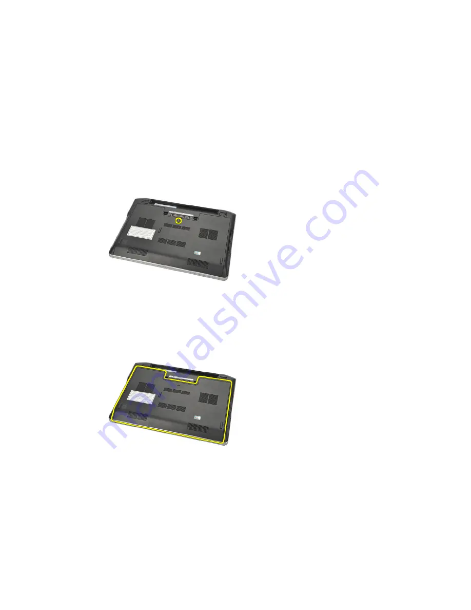
Loosen the captive screw that secures the base cover to the computer. 

4.


Slide the base cover towards the back of the computer and remove it. 

NOTE: To lift up and remove the base cover easily from the computer ensure that 
you first slide the base cover towards the back of the computer. 

Installing The Base Cover 

1.


Align in position the edge of the base cover onto the computer and slide 

it on the computer. 

2.


Tighten the screw to secure the base cover to the computer. 

21 

Summary of Contents for Latitude E6220

Page 1: ...Dell Latitude E6220 Owner s Manual Regulatory Model P15S Regulatory Type P15S001 ...

Page 2: ...emarks of Intel Corporation in the U S and other countries AMD is a registered trademark and AMD Opteron AMD Phenom AMD Sempron AMD Athlon ATI Radeon and ATI FirePro are trademarks of Advanced Micro Devices Inc Microsoft Windows MS DOS Windows Vista the Windows Vista start button and Office Outlook are either trademarks or registered trademarks of Microsoft Corporation in the United States and or ...

Page 3: ...Battery 13 3 Secure Digital SD Card 15 Removing The Secure Digital SD Card 15 Installing The Secure Digital SD Card 15 4 ExpressCard 17 Removing The ExpressCard 17 Installing The ExpressCard 17 5 Subscriber Identity Module SIM Card 19 Removing The Subscriber Identity Module SIM Card 19 Installing The Subscriber Identity Module SIM Card 19 6 Base Cover 21 Removing The Base Cover 21 Installing The B...

Page 4: ...lling The Wireless Local Access Network WLAN Card 32 11 Wireless Wide Area Network WWAN Card 33 Removing The Wireless Wide Area Network WWAN Card 33 Installing The Wireless Wide Area Network WWAN Card 34 12 Speaker 35 Removing The Speakers 35 Installing The Speakers 36 13 Palm Rest 37 Removing The Palm Rest 37 Installing The Palm Rest 38 14 Bluetooth Module 39 Removing The Bluetooth Module 39 Inst...

Page 5: ...nector 53 Removing The DC in Connector 53 Installing The DC in Connector 54 20 Wireless Switch 55 Removing The Wireless Switch 55 Installing The Wireless Switch 56 21 Hall Sensor 57 Removing The Hall Sensor 57 Installing The Hall Sensor 58 22 ExpressCard Cage 59 Removing The ExpressCard Cage 59 Installing The ExpressCard Cage 60 23 System Board 61 Removing The System Board 61 Installing The System...

Page 6: ...mera 75 Removing The Camera 75 Installing The Camera 76 29 Low Voltage Differential Signaling LVDS Camera Cable 77 Removing The Low Voltage Differential Signaling LVDS Cable 77 Installing The Low Voltage Differential Signaling LVDS Cable 78 30 Display Hinges 79 Removing The Display Hinges 79 Installing The Display Hinges 81 31 Display Top Cover 83 Removing The Display Top Cover 83 Installing The D...

Page 7: ...ications 89 34 System Setup 95 System Setup Overview 95 Entering System Setup 95 System Setup Menu Options 95 35 Diagnostics 109 Device Status Lights 109 Battery Status Lights 109 Diagnostics 109 36 Contacting Dell 113 Contacting Dell 113 ...

Page 8: ...8 ...

Page 9: ...uthorized in your product documentation or as directed by the online or telephone service and support team Damage due to servicing that is not authorized by Dell is not covered by your warranty Read and follow the safety instructions that came with the product CAUTION To avoid electrostatic discharge ground yourself by using a wrist grounding strap or by periodically touching an unpainted metal su...

Page 10: ...al outlets 6 Close the display and turn the computer upside down on a flat work surface NOTE To avoid damaging the system board you must remove the main battery before you service the computer 7 Remove the main battery see Battery 8 Turn the computer top side up 9 Open the display 10 Press the power button to ground the system board CAUTION To guard against electrical shock always unplug your comp...

Page 11: ...at the computer and all attached devices are turned off If your computer and attached devices did not automatically turn off when you shut down your operating system press and hold the power button for about 4 seconds to turn them off After Working Inside Your Computer After you complete any replacement procedure ensure you connect any external devices cards and cables before turning on your compu...

Page 12: ...a network cable first plug the cable into the network device and then plug it into the computer 3 Replace the battery 4 Connect your computer and all attached devices to their electrical outlets 5 Turn on your computer 12 ...

Page 13: ...ter 2 Slide the battery release latches to the unlock position 3 Remove the battery from the computer Installing The Battery 1 Insert the battery into its compartment 2 Rotate the battery downward until it clicks into place 3 Follow the procedures in After Working Inside Your Computer 13 ...

Page 14: ...14 ...

Page 15: ...our Computer 2 Press in on the SD card to release it from the computer 3 Grasp the SD card and pull out to release from the computer Installing The Secure Digital SD Card 1 Slide the SD card into its slot and press it until it clicks into place 2 Follow the procedures in After working inside your computer 15 ...

Page 16: ...16 ...

Page 17: ...our Computer 2 Press in on the ExpressCard to release it from the computer 3 Pull the ExpressCard out of the computer Installing The ExpressCard 1 Slide the ExpressCard into its slot and press it until it clicks into place 2 Follow the procedures in After Working Inside Your Computer 17 ...

Page 18: ...18 ...

Page 19: ...our Computer 2 Remove the battery 3 Press in on the SIM card to release it from the computer 4 Grasp the SIM card and pull out to release from the computer Installing The Subscriber Identity Module SIM Card 1 Slide the SIM card into its compartment 2 Install the battery 3 Follow the procedures in After Working Inside Your Computer 19 ...

Page 20: ...20 ...

Page 21: ...lide the base cover towards the back of the computer and remove it NOTE To lift up and remove the base cover easily from the computer ensure that you first slide the base cover towards the back of the computer Installing The Base Cover 1 Align in position the edge of the base cover onto the computer and slide it on the computer 2 Tighten the screw to secure the base cover to the computer 21 ...

Page 22: ...NOTE To insert the screw easily align the base cover correctly 3 Install the battery 4 Follow the procedures in After Working Inside Your Computer 22 ...

Page 23: ... the battery 3 Remove the base cover 4 Pry apart the retention clips securing each end of the memory module connector until the memory module pops up 5 Remove the memory NOTE DIMM A slot is the closest to the processor If there is another memory installed in the DIMM B slot repeat step 4 and 5 23 ...

Page 24: ...ory 1 Insert the memory into the memory socket 2 Press the clips to secure the memory module to the computer 3 Install the base cover 4 Install the battery 5 Follow the procedures in After Working Inside Your Computer 24 ...

Page 25: ...rive to subsequently remove any other part in the computer then do not remove the hard drive bracket and the SATA interposer NOTE The Latitude E6220 offers the SATA or M SATA hard drive 4 Remove the screws that secure the hard drive to the computer 5 Use the mylar tab to lift up the hard drive up and remove it from the computer 6 Remove the screws from the hard drive bracket 25 ...

Page 26: ...move the hard drive bracket 8 Remove the SATA interposer from the hard drive or the M SATA hard drive NOTE The SATA interposer must be removed and installed while replacing and installing the hard drive 26 ...

Page 27: ...en the hard drive bracket screws on each side 3 Place the hard drive in its compartment and connect it to the system board 4 Tighten the screws to secure the hard drive to the computer 5 Install the battery 6 Install the base cover 7 Follow the procedures in After working inside your computer 27 ...

Page 28: ...28 ...

Page 29: ...emove the M SATA hard drive to subsequently remove any other part in the computer then do not remove the hard drive bracket and the SATA interposer NOTE The Latitude E6220 offers the SATA or M SATA hard drive NOTE The SATA interposer must be removed and installed while removing and installing the M SATA hard drive 5 Remove the screws that secure the Solid State Drive SSD in place 6 Remove the SSD ...

Page 30: ...ve SSD into its slot and tighten the screws to secure the card in place 2 Attach the SATA interposer to the M SATA hard drive 3 Install the hard drive 4 Install the base cover 5 Install the battery 6 Follow the procedures in After working inside your computer 30 ...

Page 31: ... Before Working On Your Computer 2 Remove the battery 3 Remove the base cover 4 Disconnect the antenna cables from the WLAN card NOTE The WLAN antenna cables are solid colors while the WWAN antenna cables are striped 5 Remove the screw that secures the WLAN card to the computer 6 Remove the WLAN card from the computer 31 ...

Page 32: ...nto its slot 2 Connect the antenna cables to their respective connectors marked on the WLAN card 3 Replace and tighten the screw to secure the WLAN card to the computer 4 Install the base cover 5 Install the battery 6 Follow the procedures in After Working Inside Your Computer 32 ...

Page 33: ...ore Working On Your Computer 2 Remove the battery 3 Remove the base cover 4 Disconnect the antenna cables from the WWAN card NOTE The WLAN antenna cables are of solid colors while the WWAN antenna cables are striped 5 Remove the screw that secures the WWAN card to the computer 6 Remove the WWAN card from the computer 33 ...

Page 34: ...to its slot 2 Connect the antenna cables to their respective connectors marked on the WWAN card 3 Replace and tighten the screw to secure the WWAN card to the computer 4 Install the base cover 5 Install the battery 6 Follow the procedures in After Working Inside Your Computer 34 ...

Page 35: ...Before Working On Your Computer 2 Remove the battery 3 Remove the base cover 4 Disconnect the cable from the system board 5 Loosen the captive screws from the two speakers 6 Unthread the speaker cable from its holder and remove the speakers from the computer 35 ...

Page 36: ...ir slots 2 Tighten the captive screws to secure the speakers 3 Route the speaker cable along its holder 4 Connect the cable to the system board 5 Install the base cover 6 Install the battery 7 Follow the procedures in After working inside your computer 36 ...

Page 37: ...nt reader touchpad contactless smart card reader NOTE The palm rest either has a fingerprint reader along with contactless smart card modules or neither of them 6 Turn over the computer Using a plastic scribe gently pry out the top left corner of the palm rest Slide the plastic scribe along the top of the palm rest releasing all the snaps before releasing the rest of the snaps to the left right an...

Page 38: ...he computer and snap it into place 2 Connect the following cables to the system board fingerprint reader touchpad contactless smart card reader 3 Replace and tighten the screws to secure the palm rest to the computer 4 Install the base cover 5 Install the battery 6 Follow the procedures in After Working Inside Your Computer 38 ...

Page 39: ...ures in Before Working on Your Computer 2 Remove the battery 3 Remove the base cover 4 Remove the hard drive 5 Remove the cloth tape to disconnect the Bluetooth cable from the system board 6 Remove the screw securing the Bluetooth holder 7 Remove the Bluetooth holder 39 ...

Page 40: ...8 Remove the Bluetooth module and cable 9 Disconnect the cable from the Bluetooth 40 ...

Page 41: ...tooth holder on top of the Bluetooth module 4 Tighten the screw securing the holder and Bluetooth in place 5 Connect the other end of Bluetooth cable to the system board and attach it with the cloth tape 6 Install the hard drive 7 Install the base cover 8 Install the battery 9 Follow the procedures in After Working Inside Your Computer 41 ...

Page 42: ...42 ...

Page 43: ...fore Working On Your Computer 2 Remove the battery 3 Remove the base cover 4 Remove the palm rest 5 Remove the screws from the bottom chassis 6 Turn over the computer Remove the screws from the keyboard 7 Take out the keyboard and flip it over the display panel 43 ...

Page 44: ...8 Disconnect the keyboard cable from the system board 9 Remove the keyboard from the computer 44 ...

Page 45: ...ighten the screws to secure the keyboard 4 Turn over the computer and tighten the screws to secure the bottom chassis 5 Replace and tighten the screws to secure the keyboard to the palm rest 6 Install the base cover 7 Install the battery 8 Install the keyboard trim 9 Follow the procedures in After Working Inside Your Computer 45 ...

Page 46: ...46 ...

Page 47: ...omputer 2 Remove the secure digital SD card 3 Remove the battery 4 Remove the base cover 5 Remove the hard drive 6 Remove the Bluetooth module 7 Remove the speakers 8 Remove the following cables hall sensor fingerprint reader touchpad smart card reader 9 Remove the screws from the bottom chassis 47 ...

Page 48: ... the bottom chassis to the computer and press the Certificate of Authenticity COA label in place 2 Tighten the screws to secure the bottom chassis 3 Connect the following cables hall sensor fingerprint reader touchpad smart card reader 4 Install the speakers 5 Install the Bluetooth module 6 Install the hard drive 7 Install the base cover 8 Install the battery 9 Install the secure digital SD Card 1...

Page 49: ...puter 2 Remove the secure digital SD card 3 Remove the battery 4 Remove the base cover 5 Remove the hard drive 6 Remove the Bluetooth module 7 Remove the speakers 8 Remove the bottom chassis 9 Disconnect the coin cell battery cable from the system board 10 Remove the coin cell battery from the computer 49 ...

Page 50: ...ess the coin cell battery into its slot 3 Install the speakers 4 Install the Bluetooth module 5 Install the hard drive 6 Install the base cover 7 Install the battery 8 Install the secure digital SD Card 9 Install the bottom chassis 10 Follow the procedures in After working inside your computer 50 ...

Page 51: ...emove the battery 4 Remove the base cover 5 Remove the hard drive 6 Remove the Bluetooth module 7 Remove the speakers 8 Remove the bottom chassis 9 Disconnect the CPU fan cable from the system board 10 Loosen the captive screws from the heat sink and remove the screw from the CPU fan 11 Remove the heat sink and the CPU fan assembly 51 ...

Page 52: ...nk and CPU fan 3 Connect the CPU fan cable to the system board 4 Install the bottom chassis 5 Install the speakers 6 Install the Bluetooth module 7 Install the hard drive 8 Install the base cover 9 Install the battery 10 Install the secure digital SD Card 11 Follow the procedures in After Working Inside Your Computer 52 ...

Page 53: ...mputer 2 Remove the secure digital SD card 3 Remove the battery 4 Remove the base cover 5 Remove the hard drive 6 Remove the Bluetooth module 7 Remove the speakers 8 Remove the bottom chassis 9 Disconnect the DC In cable from the system board 10 Lift and remove the DC In connector from the computer 53 ...

Page 54: ...the DC In cable to the system board 3 Install the bottom chassis 4 Install the speakers 5 Install the Bluetooth module 6 Install the hard drive 7 Install the base cover 8 Install the battery 9 Install the secure digital SD Card 10 Follow the procedures in After Working Inside Your Computer 54 ...

Page 55: ...the secure digital SD card 3 Remove the battery 4 Remove the base cover 5 Remove the hard drive 6 Remove the Bluetooth module 7 Remove the speakers 8 Remove the bottom chassis 9 Disconnect the wireless switch cable from the system board 10 Remove the screw securing the wireless switch 11 Remove the wireless switch 55 ...

Page 56: ...itch in place 3 Connect the wireless switch cable to the system board 4 Install the bottom chassis 5 Install the speakers 6 Install the Bluetooth module 7 Install the hard drive 8 Install the base cover 9 Install the battery 10 Install the secure digital SD Card 11 Follow the procedures in After Working Inside Your Computer 56 ...

Page 57: ...Your Computer 2 Remove the secure digital SD card 3 Remove the battery 4 Remove the base cover 5 Remove the hard drive 6 Remove the Bluetooth module 7 Remove the speakers 8 Remove the bottom chassis 9 Remove the screw securing the hall sensor 10 Remove the hall sensor with its cable 57 ...

Page 58: ...w to secure the hall sensor 3 Install the bottom chassis 4 Install the speakers 5 Install the Bluetooth module 6 Install the hard drive 7 Install the base cover 8 Install the battery 9 Install the secure digital SD Card 10 Follow the procedures in After Working Inside Your Computer 58 ...

Page 59: ...ve the secure digital SD card 3 Remove the battery 4 Remove the base cover 5 Remove the hard drive 6 Remove the Bluetooth module 7 Remove the speakers 8 Remove the bottom chassis 9 Disconnect the flex cable from the system board 10 Remove the screws securing the ExpressCard cage 11 Slide out the ExpressCard cage 59 ...

Page 60: ...he screws to secure the ExpressCard cage 3 Connect the flex cable to the system board 4 Install the bottom chassis 5 Install the speakers 6 Install the bluetooth module 7 Install the hard drive 8 Install the base cover 9 Install the battery 10 Install the secure digital SD Card 11 Follow the procedures in After Working Inside Your Computer 60 ...

Page 61: ...7 Remove the hard drive 8 Remove the Wireless Local Access Network WLAN card 9 Remove the Wireless Wide Area Network WWAN card 10 Remove the Bluetooth module 11 Remove the speakers 12 Remove the palm rest 13 Remove the keyboard 14 Remove the bottom chassis 15 Remove the heatsink 16 Remove the DC in Connector 17 Remove the coin cell battery 18 Remove the screws securing the Low voltage differential...

Page 62: ...20 Disconnect the LVDS cable 21 Turn the computer over and disconnect the following cables from the system board wireless switch express card 22 Remove the screws securing the system board 62 ...

Page 63: ...talling The System Board 1 Insert the wireless antenna cables through the system board opening 2 Align the system board properly with the eSATA USB headphone microphone and VGA port connectors fitting into the apertures NOTE The left and right connectors should fit properly If not re adjust the system board position to align them 3 Tighten the screws securing the system board in place 4 Connect th...

Page 64: ...bottom chassis 11 Install the keyboard 12 Install the palm rest 13 Install the speakers 14 Install the Bluetooth module 15 Install the Wireless Wide Area Network WWAN card 16 Install the Wireless Local Area Network WLAN card 17 Install the hard drive 18 Install the memory 19 Install the base cover 20 Install the subscriber identity module SIM card 21 Install the battery 22 Install the secure digit...

Page 65: ...rd drive 8 Remove the Wireless Local Access Network WLAN card 9 Remove the Wireless Wide Area Network WWAN card 10 Remove the Bluetooth module 11 Remove the speakers 12 Remove the palm rest 13 Remove the keyboard 14 Remove the bottom chassis 15 Remove the heatsink 16 Remove the DC in Connector 17 Remove the coin cell battery 18 Remove the system board 19 Remove the screw that secures the smart car...

Page 66: ...hassis 8 Install the keyboard 9 Install the palm rest 10 Install the speakers 11 Install the bluetooth module 12 Install the Wireless Wide Area Network WWAN card 13 Install the Wireless Local Area Network WLAN card 14 Install the hard drive 15 Install the memory 16 Install the base cover 17 Install the subscriber identity module SIM card 18 Install the battery 19 Install the secure digital SD Card...

Page 67: ... battery 3 Remove the base cover 4 Remove the palm rest 5 Remove the keyboard 6 Remove the screws from the bottom chassis 7 Disconnect all the wireless antenna cables 8 Turn over the computer and lift it up slightly Pull out the wireless antenna cables from the opening in the computer and unthread them from the holder 67 ...

Page 68: ...9 Remove the screws from the Low Voltage Differential Signalling LVDS bracket 10 Remove the LVDS bracket 11 Disconnect the LVDS cable from the system board 12 Remove the screws from the hinges 68 ...

Page 69: ...omputer Installing The Display Assembly 1 Align the display hinges on the computer 2 Replace and tighten the screws on the hinges 3 Connect the Low Voltage Differential Signaling LVDS cable to the system board 4 Install the LVDS bracket and replace and tighten the screws to secure it 5 Insert the wireless antenna cables into the holder Lift the back of the computer slightly and insert the wireless...

Page 70: ...e computer Connect the wireless antenna cables to their respective modules 7 Replace and tighten the screws on the bottom chassis 8 Install the keyboard 9 Install the palm rest 10 Install the base cover 11 Install the battery 12 Follow the procedures in After Working Inside Your Computer 70 ...

Page 71: ...he top left corner of the display bezel Slide the plastic scribe along the top side of the bezel before moving left to release all the snaps NOTE The bottom of the bezel is firmly attached with snaps and adhesive tape thus the technician needs to be careful when separating the bottom of the display bezel from the display assembly 4 Remove the display bezel 71 ...

Page 72: ...to the display assembly and align them up on the computer 2 Press along the bottom of the bezel before moving on to the left right and top until all the snaps are in place 3 Install the battery 4 Follow the procedures in After Working Inside Your Computer 72 ...

Page 73: ...rking On Your Computer 2 Remove the battery 3 Remove the display bezel 4 Remove the screws from the display panel 5 Rotate the display panel over to the keyboard 6 Peel of the adhesive tape that secures the Low Voltage Differential Signalling LVDS connection to the display panel 73 ...

Page 74: ...ard 2 Connect the Low Voltage Differential Signalling LVDS cable to the display panel and attach the adhesive tape to secure the connection 3 Rotate the display panel upwards into its compartment 4 Replace and tighten the screws to secure the display panel 5 Install the display bezel 6 Install the battery 7 Follow the procedures in After Working Inside Your Computer 74 ...

Page 75: ...l NOTE The computer has either a camera with a microphone module or a microphone only module Either of them resides in the same slot 4 Disconnect the cable from the camera and or microphone module 5 Remove the screw that secures the module 6 Remove the camera and or microphone by disconnecting from the cable on the display top cover 75 ...

Page 76: ...or microphone module to its cable on the display top cover 2 Attach the module into its compartment and tighten the screw to secure it 3 Install the display bezel 4 Install the battery 5 Follow the procedures in After Working Inside Your Computer 76 ...

Page 77: ...omputer 2 Remove the battery 3 Remove the base cover 4 Remove the palm rest 5 Remove the keyboard 6 Remove the display assembly 7 Remove the display bezel 8 Remove the display panel 9 Disconnect the LVDS Camera Microphone cable assembly from the camera and or microphone module 10 Peel off the LVDS Camera Microphone cable assembly from the top cover and remove it 77 ...

Page 78: ...era and or microphone module 2 Align the cable and attach it to the top cover 3 Install the display panel 4 Install the display bezel 5 Install the display assembly 6 Install the keyboard 7 Install the palm rest 8 Install the base cover 9 Install the battery 10 Follow the procedures in After Working Inside Your Computer 78 ...

Page 79: ...e the battery 3 Remove the base cover 4 Remove the palm rest 5 Remove the keyboard 6 Remove the display assembly 7 Remove the display bezel 8 Remove the display panel 9 Remove the screws that secure the hinge 10 Release the wireless cable from within the hinge cap 11 Rotate the hinge sideways until it is free 79 ...

Page 80: ...12 Remove the screw that secures the hinge cap 13 Slide off the hinge cap from the hinge Repeat all the steps to remove the other hinge 80 ...

Page 81: ...de in and rotate the hinge onto the display top cover 4 Replace and tighten the screws to secure the hinge in place 5 Install the display panel 6 Install the display bezel 7 Install the display assembly 8 Install the keyboard 9 Install the palm rest 10 Install the base cover 11 Install the battery 12 Follow the procedures in After Working Inside Your Computer 81 ...

Page 82: ...82 ...

Page 83: ... the battery 3 Remove the base cover 4 Remove the palm rest 5 Remove the keyboard 6 Remove the display assembly 7 Remove the display bezel 8 Remove the display panel 9 Remove the camera and microphone 10 Remove the low voltage differential signalling LVDS cable 11 Remove the display hinges 12 Remove the display cover 83 ...

Page 84: ... differential signalling LVDS cable 4 Install the camera and microphone 5 Install the display panel 6 Install the display bezel 7 Install the display assembly 8 Install the keyboard 9 Install the palm rest 10 Install the base cover 11 Install the battery 12 Follow the procedures in After Working Inside Your Computer 84 ...

Page 85: ...rive 9 Remove the Wireless Local Access Network WLAN card 10 Remove the Wireless Wide Area Network WWAN card 11 Remove the Bluetooth module 12 Remove the speakers 13 Remove the palm rest 14 Remove the keyboard 15 Remove the bottom chassis 16 Remove the heatsink 17 Remove the DC in Connector 18 Remove the wireless switch 19 Remove the hall sensor 20 Remove the ExpressCard cage 21 Remove the system ...

Page 86: ...86 ...

Page 87: ...tom chassis 11 Install the keyboard 12 Install the palm rest 13 Install the speakers 14 Install the bluetooth module 15 Install the Wireless Wide Area Network WWAN card 16 Install the Wireless Local Area Network WLAN card 17 Install the hard drive 18 Install the memory 19 Install the base cover 20 Install the subscriber identity module SIM card 21 Install the battery 22 Install the ExpressCard 23 ...

Page 88: ...88 ...

Page 89: ...quired by law to ship with your computer For more information regarding the configuration of your computer click Start Help and Support and select the option to view information about your computer System Information Chipset Intel Mobile QM67 Enhanced Chipset DRAM bus width 64 bit Flash EPROM SPI 32 Mbits PCIe Gen1 bus 100 MHz Processor Types Intel Core i3 series Intel Core i5 series Intel Core i7...

Page 90: ...log Interface Internal high definition audio External microphone in stereo headphones external speakers connector Speakers two Internal speaker amplifier 2 W typical per channel Volume controls keyboard function keys program menus Video Video type integrated on system board Data bus integrated video Video controller Intel HD Graphics 3000 Video memory 512 MB Communications Network adapter 10 100 1...

Page 91: ...P Desfire Display Type white Light Emitting Diode WLED display Size 12 5 inch high definition HD Dimensions Height 300 40 mm 7 58 inches Width 324 00 mm 12 76 inches Diagonal 355 60 mm 14 00 inches Active area X Y 309 40 mm x 173 95 mm Maximum resolution 1366 x 768 pixels at 262K colors Maximum Brightness 200 nits Operating angle 0 closed to 135 Refresh rate 60 Hz Minimum Viewing angles Horizontal...

Page 92: ...ight 19 80 mm 0 78 inches Width 208 00 mm 8 19 inches 6 ell Depth 54 10 mm 2 13 inches Height 20 85 mm 0 82 inches Width 214 00 mm 8 43 inches Weight 3 cell 177 00 g 0 39 lb 6 cell 349 00 g 0 77 lb Charge time for a 4 cell and 6 cell approximately 1 hour to 80 capacity and 2 battery with computer off with 90 W hours to 100 capacity adapter Voltage 11 10 VDC Temperature range Operating 0 C to 35 C ...

Page 93: ...nd 90 W Input voltage 100 VAC to 240 VAC Input current maximum 1 50 A Input frequency 50 Hz to 60 Hz Output power 65 W 90 W Output current 65 W 3 34 A continuous 90 W 4 62 A continuous Rated output voltage 19 5 1 0 VDC Temperature range Operating 0 C to 40 C 32 F to 104 F Non Operating 40 C to 70 C 40 F to 158 F Physical Height 24 65 mm 0 97 inches Width 309 00 mm 12 16 inches Depth 226 00 mm 8 89...

Page 94: ...to 90 noncondensing Storage 5 to 95 noncondensing Altitude maximum Operating 15 20 m to 3048 m 50 ft to 10 000 ft Non Operating 15 20 m to 10 668 m 50 ft to 35 000 ft Airborne contaminant level G1 as defined by ISA 71 04 1985 94 ...

Page 95: ...rk incorrectly Entering System Setup 1 Turn on or restart your computer 2 When the blue DELL logo is displayed you must watch for the F2 prompt to appear 3 Once the F2 prompt appears press F2 immediately NOTE The F2 prompt indicates that the keyboard has initialized This prompt can appear very quickly so you must watch for it to display and then press F2 If you press F2 before you are prompted thi...

Page 96: ...e Internal HDD USB Storage Device CD DVD CD RW Drive Onboard NIC Cardbus NIC You can also choose the Boot List option The options are Legacy UEFI Date Time System Configuration Allows you to change the date and time The following table describe the menu options of the System Configuration menu Option Description NOTE System Configuration contains options and settings related to integrated system d...

Page 97: ...SH ASF 2 0 Allows you to configure the parallel port on the docking station The options are Disabled AT PS2 ECP Serial Port Default Setting AT Allows you to configure the integrated serial port The options are Disabled COM1 COM2 COM3 COM4 SATA Operation Default Setting COM1 Allows you to configure the internal SATA hard drive controller The options are Disabled ATA AHCI RAID On Default Setting RAI...

Page 98: ...ed during system start up Miscellaneous Devices Allows you to enable or disable the following devices Internal Modem Microphone eSATA Ports Hard Drive Free Fall Protection Module Bay ExpressCard Camera You can also enable or disable Media Card and 1394 Enable Media Card only Disable Media Card and 1394 Default Setting Media Card and 1394 Keyboard illumination Allows you to configure the keyboard i...

Page 99: ...uccessful password changes take effect immediately Default Setting Not set System Password Allows you to set change or delete the system password Drives Allows you to configure the SATA drives on board The options are SATA 0 SATA 4 SATA 5 Default Setting All drives are enabled Video The following table describe the menu options of the Video menu Option Description LCD Brightness Allows you to set ...

Page 100: ...assword Bypass Disabled Reboot bypass Password Change Default Setting Disabled Allows you to enable the disable permission to the System and Hard Drive passwords when the admin password is set Default Setting Allow Non Admin Password Changes is selected Allows you to enforce the option to always set strong passwords Default Setting Disabled Allows you to enable the Trusted Platform Module TPM duri...

Page 101: ... by the admin password Default Setting Disabled Password Configuration Allows you to determine the minimum and maximum length of Administrator and System passwords Admin Setup Lockout Allows you to prevent users from entering Setup when an Administrator password is set Default Setting Disabled Performance The following table describe the menu options of the Performance menu Option Description Mult...

Page 102: ...ault Setting Enabled Allows you to enable or disable the HyperThreading in the processor Default Setting Enabled Power Management The following table describe the menu options of the Power Management menu Option Description AC Behavior Allows you to enable or disable the computer from turning on automatically when an AC adapter is connected Default Setting Disabled Auto On Time Allows you to set t...

Page 103: ...ered by a special LAN signal or from Hibernate state when triggered by a special wireless LAN signal Wake up from the Standby state is unaffected by this setting and must be enabled in the operating system This feature only works when the computer is connected to AC Disabled Does not allow the system to power on when it receives a wake up signal from the LAN or wireless LAN LAN Only Allows the sys...

Page 104: ...u to choose one or two methods to enable the keypad that is embedded in the internal keyboard Fn Key Only By Num Lk Default Setting Fn Key Only Mouse Touchpad Allows you to define how the system handles mouse and touchpad input The options are Serial Mouse PS2 Mouse Touchpad PS 2 Mouse Default Setting Touchpad PS 2 Mouse Numlock Enable Allows you to enable the Numlock option when the computer boot...

Page 105: ...enu options of the Virtualization Support menu Option Description Virtualization Allows you to enable or disable the Intel Virtualization Technology Default Setting Enable Intel Virtualization Technology is selected VT for Direct I O Allows you to enable or disable Virtualization Technology for Direct I O Default Setting Disabled is selected Trusted Execution This option specifies wether a Measure...

Page 106: ...ntenance The following table describe the menu options of the Maintenance menu Option Description Service Tag Displays the Service Tag of your computer NOTE If a Service Tag has not been set for this system the computer will automatically bring up this screen when users enter the BIOS You will be prompted to enter the Service Tag Asset Tag Displays the Asset Tag SERR Messages This filed controls t...

Page 107: ...nd clear the System Setup BIOS POST events DellDiag Events Allows you to view and clear the DellDiag events Thermal Events Allows you to view and clear the Thermal events Power Events Allows you to view and clear the Power events 107 ...

Page 108: ...108 ...

Page 109: ...outlet the battery light operates as follows Alternately blinking amber light and white light An unauthenticated or unsupported non Dell AC adapter is attached to your laptop Alternately blinking amber light with steady white light Temporary battery failure with AC adapter present Constantly blinking amber light Fatal battery failure with AC adapter present Light off Battery in full charge mode wi...

Page 110: ...ed to an electrical outlet the battery light operates as follows Alternately blinking amber light and white light An unauthenticated or unsupported non Dell AC adapter is attached to your laptop Alternately blinking amber light with steady white light Temporary battery failure with AC adapter present Constantly blinking amber light Fatal battery failure with AC adapter present Light off Battery in...

Page 111: ...ponent is faulty Blinking Blinking Solid The video card is preventing the system from completing POST Blinking Blinking Off The keyboard is preventing the system from completing POST Blinking Off Blinking The USB controller encountered a problem during initialization Solid Blinking Blinking No SODIMMs are installed Blinking Solid Blinking The LCD encountered a problem during initialization Off Bli...

Page 112: ...112 ...

Page 113: ...isit support dell com 2 Verify your country or region in the Choose a Country Region drop down menu at the bottom of the page 3 Click Contact Us on the left side of the page 4 Select the appropriate service or support link based on your need 5 Choose the method of contacting Dell that is convenient for you 113 ...

Page 114: ......

Reviews: