background image

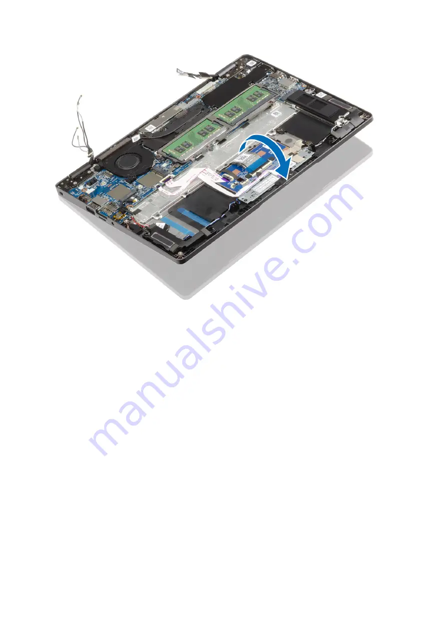
4. Connect the touch screen cable to the connector on the system board and adhere the adhesive tape [1].
5. Reroute the eDP cable and connect it to the eDP connector [2].
6. Place the eDP cable bracket on the system board [3].
7. Replace the single (M2x4) screw that secures the eDP cable bracket to the system board [4].

74

Komponentide eemaldamine ja paigaldamine

Summary of Contents for Latitude 5300 2-in-1 Chrome

Page 1: ...Dell Latitude 5300 2 in 1 Chrome Service Manual Regulatory Model P96G Regulatory Type P96G01 ...

Page 2: ...tvarakahjustust või andmekadu ja annab teavet probleemi vältimise kohta HOIATUS HOIATUS tähistab võimalikku omandi kahjustumist või inimeste vigastusi või surma 2019 Dell Inc või selle tütarettevõtted Kõik õigused on kaitstud Dell EMC ja muud kaubamärgid on ettevõtte Dell Inc või selle tütarettevõtete kaubamärgid Muud kaubamärgid kuuluvad nende omanikele 2020 01 Rev A00 ...

Page 3: ...amine ja paigaldamine 11 Recommended tools 11 Screw List 11 Lahtivõtmine ja kokkupanek 12 microSD kaart 12 SIM kaardi salv 14 tagakaas 17 aku 22 Mälumoodulid 26 WWAN kaart 28 WLAN kaart 30 Pooljuhtketas 32 Kõlarid 36 Ventilaator 41 Jahutusradiaator 45 Toiteadapteri pesa 46 LED paneel 50 Puuteplaadi nupupaneel 56 Emaplaat 59 Nööppatarei 68 Ekraanisõlm 69 Klaviatuur 75 Randmetoe koost 81 4 Tõrkeotsi...

Page 4: ...ering the Chromebook 101 Reset Chromebook 103 LCD sisseehitatud enesetest 107 Diagnostic LEDs 108 M BIST 109 Diagnostics 109 Valideerimistööriistad 114 5 Lisateave ja Delliga ühendust võtmine 121 4 Contents ...

Page 5: ... märgitud eeldatakse igas selle dokumendi protseduuris et on täidetud järgmised tingimused Olete lugenud arvutiga kaasas olevat ohutusteavet Komponendi saab asendada või kui see on eraldi ostetud paigaldada eemaldamisprotseduurile vastupidises järjekorras See ülesanne MÄRKUS Enne arvuti kaane või paneelide avamist ühendage lahti kõik toiteallikad Pärast arvuti sisemuses tegutsemise lõpetamist pang...

Page 6: ...d Lülitage süsteem ja kõik ühendatud välisseadmed välja Lahutage süsteemi ja kõigi ühendatud välisseadmete vahelduvvoolutoide Eemaldage süsteemi küljest kõik võrgukaablid telefoni ja telekommunikatsioonijuhtmed Elektrostaatilisest lahendusest ESD põhjustatud kahjustuste vältimiseks kasutage sisemuses töötades ESD välikomplekti Pärast mis tahes süsteemi osa eemaldamist asetage see ettevaatlikult an...

Page 7: ...iga ja süsteemi mis tahes metallosaga millega parajasti töötate Õigesti paigaldatud hooldusosi saab ESD kotist välja võtta ja otse matile asetada ESD tundlikud esemed on ohutus kohas teie käes ESD matil süsteemis või kotis Randmerihm ja ühenduskaabel randmerihm ja ühenduskaabel võivad olla otse ühendatud teie randmega ja riistvara küljes oleva metallosaga kui ESD matti ei ole vaja või antistaatili...

Page 8: ...anilist tõsteseadet 1 Võtke kindel tasakaalustatud jalgade asend Hoidke jalad lahus et need oleksid stabiilse aluse eest ja suunake oma varbad välja 2 Pinguldage kõhulihaseid Kõhulihased toetavad tõstmisel selgroogu kompenseerides koormuse jõudu 3 Tõstke oma jalgade mitte seljaga 4 Hoidke koormust enda lähedal Mida lähemal on see seljale seda vähem jõudu avaldab see seljaosale 5 Koormuse tõstmisel...

Page 9: ...Major components of your system 1 Base cover 2 Power adapter port 2 Major components of your system 9 ...

Page 10: ...d button board 13 Display assembly 14 WLAN card 15 System fan 16 Heatsink NOTE Dell provides a list of components and their part numbers for the original system configuration purchased These parts are available according to warranty coverages purchased by the customer Contact your Dell sales representative for purchase options 10 Major components of your system ...

Page 11: ...is table shows the screw list and the images for the Dell Latitude 5300 2 in 1 Chrome for different components Table 1 Screw Size List Component Screw type Quantity Image Base cover M2 5x6 5 captive screws NOTE Screws are part of the base cover 8 Battery M2x5 captive screws 2 WWAN M2x3 1 WLAN M2x2 1 SSD support bracket M2x3 2 SSD M2x2 big head 1 LED board M2x2 5 big head 1 Fan M2x5 2 eDP bracket M...

Page 12: ...2 Keyboard support bracket M2x2 19 Keyboard M2x2 5 Lahtivõtmine ja kokkupanek microSD kaart Removing the microSD card Prerequisites 1 Follow the procedure in before working inside your computer Steps 1 Push the microSD card to release it from the computer 1 2 Slide the microSD card out of the computer 2 12 Komponentide eemaldamine ja paigaldamine ...

Page 13: ...Installing the microSD card Steps 1 Align the microSD card to its slot on the computer 1 2 Slide the microSD card into the slot until it clicks into place 2 Komponentide eemaldamine ja paigaldamine 13 ...

Page 14: ...the SIM card tray Prerequisites 1 Follow the procedure in before working inside your computer Steps 1 Insert a pin into the hole of the SIM card tray and push inward until the tray is released 1 2 2 Slide the SIM card tray out of the computer 3 14 Komponentide eemaldamine ja paigaldamine ...

Page 15: ...Installing the SIM card tray Steps 1 Place the SIM card into the SIM card tray with the metallic contact facing up 1 Komponentide eemaldamine ja paigaldamine 15 ...

Page 16: ... SIM card tray with SIM card 2 Align the SIM card tray with the slot on the computer and carefully slide it in 2 3 Slide the SIM card tray into the slot until it clicks into place 3 16 Komponentide eemaldamine ja paigaldamine ...

Page 17: ...procedures in after working inside your computer tagakaas Removing the base cover Prerequisites 1 Follow the procedure in before working inside your computer 2 Remove the microSD card Steps 1 Loosen the eight captive screws 1 Komponentide eemaldamine ja paigaldamine 17 ...

Page 18: ...2 Using a plastic scribe 1 pry the base cover from the top left corner and continue to work on the sides to open the base cover 2 18 Komponentide eemaldamine ja paigaldamine ...

Page 19: ...3 Lift and remove the base cover away from the computer Installing the base cover Steps 1 Align and place the base cover on the computer Komponentide eemaldamine ja paigaldamine 19 ...

Page 20: ...2 Press the edges and sides of the base cover until it snaps into place 20 Komponentide eemaldamine ja paigaldamine ...

Page 21: ...3 Tighten the eight captive screws to secure the base cover to the computer Komponentide eemaldamine ja paigaldamine 21 ...

Page 22: ...selle toote hooldamise ajal poleks kruvid kadunud ega valesti paigaldatud et vältida aku ja teiste süsteemikomponentide juhuslikku torkamist või kahjustumist Kui aku on paisumise tulemusena arvutis kinni ärge üritage seda vabaks kangutada kuna liitium ioonaku torkamine painutamine või purustamine võib olla ohtlik Sellisel juhul võtke abi saamiseks ühendust Delli tehnilise toega Vt www dell com con...

Page 23: ...3 Loosen the two captive screws that secure the battery to the palmrest 1 4 Slide the battery inward and lift the battery away from the palmrest 2 Komponentide eemaldamine ja paigaldamine 23 ...

Page 24: ...Installing the battery Steps 1 Align and slide the battery on the palmrest 1 2 Tighten the two captive screws to secure the battery to the palmrest 2 24 Komponentide eemaldamine ja paigaldamine ...

Page 25: ...3 Connect the battery cable to the connector on the system board 1 4 Affix the adhesive tape to secure the battery cable connector 2 Komponentide eemaldamine ja paigaldamine 25 ...

Page 26: ... module Prerequisites 1 Follow the procedure in before working inside your computer 2 Remove the microSD card 3 Remove the SIM card tray 4 Remove the base cover 5 Disconnect the battery cable Steps 1 Pry the retention clips securing the memory module until the memory module pops up 1 2 Remove the memory module from the memory module slot 2 26 Komponentide eemaldamine ja paigaldamine ...

Page 27: ...ith the tab on the memory module slot 2 Slide the memory module firmly into the slot at an angle 1 3 Press the memory module down until the clips secure it 2 NOTE If you do not hear the click remove the memory module and reinstall it Komponentide eemaldamine ja paigaldamine 27 ...

Page 28: ...r 2 Remove the microSD card 3 Remove the SIM card tray 4 Remove the base cover 5 Disconnect the battery cable Steps 1 Loosen the single M2x3 captive screw that secures the WWAN card bracket to the system board 1 2 Remove the WWAN card bracket with screw that secures the WWAN antenna cables 2 3 Disconnect the WWAN antenna cables from the connectors on the WWAN card 3 4 Slide and lift the WWAN card ...

Page 29: ...rd into the connector on the system board 1 2 Connect the WWAN antenna cables to the connectors on the WWAN card 2 3 Place the WWAN card bracket with screw to secure the WWAN antenna cables to the WWAN card 3 4 Tighten the single M2x3 captive screw to secure the WWAN card bracket to the WWAN card 4 Komponentide eemaldamine ja paigaldamine 29 ...

Page 30: ...puter 2 Remove the microSD card 3 Remove the SIM card tray 4 Remove the base cover 5 Disconnect the battery cable Steps 1 Loosen the single M2x2 screw that secures the WLAN card bracket to the system board 1 2 Remove the WLAN card bracket with screw that secures the WLAN antenna cables 2 3 Disconnect the WLAN antenna cables from the connectors on the WLAN card 3 4 Slide and lift the WLAN card away...

Page 31: ...rd into the connector on the system board 1 2 Connect the WLAN antenna cables to the connectors on the WLAN card 2 3 Place the WLAN card bracket with screw to secure the WLAN antenna cables to the WLAN card 3 4 Tighten the single M2x3 captive screw to secure the WLAN card bracket to the WLAN card 4 Komponentide eemaldamine ja paigaldamine 31 ...

Page 32: ...he M 2 SSD Prerequisites 1 Follow the procedure in before working inside your computer 2 Remove the microSD card 3 Remove the SIM card tray 4 Remove the base cover 5 Disconnect the battery cable Steps 1 Remove the two M2x3 screws that secure the M 2 SSD support bracket to the palmrest 1 2 Slightly turn and remove the SSD support bracket from the M 2 SSD slot 2 32 Komponentide eemaldamine ja paigal...

Page 33: ...3 Remove the single M2x2 screw that secures the M 2 SSD to the palmrest 1 4 Lift the M 2 SSD away from the computer 2 Komponentide eemaldamine ja paigaldamine 33 ...

Page 34: ...Installing the M 2 SSD Steps 1 Place the M 2 SSD into the slot on the palmrest 1 2 Replace the single M2x2 screw to secure the M 2 SSD to the palmrest 2 34 Komponentide eemaldamine ja paigaldamine ...

Page 35: ...3 Align and place the SSD support bracket above the M 2 SSD 1 4 Replace the two M2x3 screws to secure the SSD support bracket to the palmrest 2 Komponentide eemaldamine ja paigaldamine 35 ...

Page 36: ...rking inside your computer Kõlarid Removing the speakers Prerequisites 1 Follow the procedure in before working inside your computer 2 Remove the microSD card 3 Remove the SIM card tray 4 Remove the base cover 5 Remove the battery Steps 1 Disconnect the LED board cable from the connector on the system board 1 36 Komponentide eemaldamine ja paigaldamine ...

Page 37: ...t the touchpad button board cable from the touchpad module 2 3 Peel the adhesive tapes and unroute the speaker cable 1 4 Peel the adhesive tape from the speaker cable 2 Komponentide eemaldamine ja paigaldamine 37 ...

Page 38: ...5 Lift and remove the speakers away from the palmrest 38 Komponentide eemaldamine ja paigaldamine ...

Page 39: ...and rubber grommets place the speakers in the slots on the palmrest 2 Route the speaker cable through the routing guides 1 3 Replace the adhesive tape to secure the speaker cable and connect it to the system board 2 Komponentide eemaldamine ja paigaldamine 39 ...

Page 40: ...4 Connect the LED board cable to the system board 1 5 Connect the touchpad button cable to the touchpad module 2 40 Komponentide eemaldamine ja paigaldamine ...

Page 41: ... inside your computer Ventilaator Removing the system fan Prerequisites 1 Follow the procedure in before working inside your computer 2 Remove the microSD card 3 Remove the SIM card tray 4 Remove the base cover 5 Remove the battery Steps 1 Disconnect the system fan cable from the connector on the system board Komponentide eemaldamine ja paigaldamine 41 ...

Page 42: ...2 Remove the two M2x5 screws that secure the system fan to the palmrest 1 3 Lift the system fan away from the computer 2 42 Komponentide eemaldamine ja paigaldamine ...

Page 43: ...m fan Steps 1 Place and align the screw holes on the system fan with the screw holes on to the palmrest 1 2 Replace the two M2x5 screws to secure the system fan to the palmrest 2 Komponentide eemaldamine ja paigaldamine 43 ...

Page 44: ...3 Connect the system fan cable to the connector on the system board 44 Komponentide eemaldamine ja paigaldamine ...

Page 45: ...ollow the procedure in before working inside your computer 2 Remove the microSD card 3 Remove the SIM card tray 4 Remove the base cover 5 Remove the battery Steps 1 Loosen the four captive screws that secure the heatsink to the system board 1 NOTE Loosen the screws in the order of the callout numbers 1 2 3 4 as indicated on the heatsink 2 Lift the heatsink away from the system board 2 Komponentide...

Page 46: ... to the system board 2 Next steps 1 Replace the battery 2 Replace the base cover 3 Replace the SIM card tray 4 Replace the microSD card 5 Follow the procedure in after working inside your computer Toiteadapteri pesa Removing the power adapter port Prerequisites 1 Follow the procedure in before working inside your computer 2 Remove the microSD card 3 Remove the SIM card tray 4 Remove the base cover...

Page 47: ...Type C bracket to the system board 1 2 Lift the Type C bracket away from the computer 2 3 Disconnect the DC in port cable from the connector on the system board and remove the DC in port from the computer 1 2 Komponentide eemaldamine ja paigaldamine 47 ...

Page 48: ...stalling the power adapter port Steps 1 Place the DC in port to its slot on the computer 1 2 Connect the DC in port cable to the connector on the system board 2 48 Komponentide eemaldamine ja paigaldamine ...

Page 49: ...3 Place the Type C bracket on its slot on the computer 1 4 Replace the two M2x4 screws to secure the Type C bracket to the palmrest 2 Komponentide eemaldamine ja paigaldamine 49 ...

Page 50: ...puter LED paneel Removing the LED board Prerequisites 1 Follow the procedure in before working inside your computer 2 Remove the microSD card 3 Remove the SIM card tray 4 Remove the base cover 5 Remove the battery Steps 1 Disconnect the LED board cable from the connector on the system board 1 2 Unroute the LED board cable 2 50 Komponentide eemaldamine ja paigaldamine ...

Page 51: ...3 Peel the adhesive tape that secures the LED board cable connector to the LED board 1 4 Peel the grey adhesive tape that secures the LED board 2 Komponentide eemaldamine ja paigaldamine 51 ...

Page 52: ...5 Remove the single M2x2 5 screw that secures LED board to the palmrest 1 6 Lift the LED board away from the computer 2 52 Komponentide eemaldamine ja paigaldamine ...

Page 53: ...Steps 1 Place the LED board and align the screw hole on the LED board with the screw hole on the palmrest 1 2 Replace the single M2x2 5 screw to secure the LED board to the palmrest 2 Komponentide eemaldamine ja paigaldamine 53 ...

Page 54: ...3 Affix the grey adhesive tape to secure the LED board 1 4 Affix the adhesive tape to secure the LED board 2 54 Komponentide eemaldamine ja paigaldamine ...

Page 55: ...5 Route the LED board cable 1 and connect the LED board cable to the connector on the system board 2 Komponentide eemaldamine ja paigaldamine 55 ...

Page 56: ...e in before working inside your computer 2 Remove the microSD card 3 Remove the SIM card tray 4 Remove the base cover 5 Remove the battery 6 Remove the LED board Steps 1 Open the latch and disconnect the touchpad button board cable from the connector on the touchpad board 2 Remove the two M2x3 screws that secure the touchpad button bracket to the palmrest 1 3 Lift the touchpad button board bracket...

Page 57: ...uchpad button board Steps 1 Place the touchpad button board into the slot on the palmrest 1 2 Replace the two M2x3 screws to secure the touchpad button board to the palmrest 2 Komponentide eemaldamine ja paigaldamine 57 ...

Page 58: ...3 Connect the touchpad button board cable to the connector on the touchpad board 58 Komponentide eemaldamine ja paigaldamine ...

Page 59: ...y 6 Remove the memory module 7 Remove the WWAN card 8 Remove the WLAN card 9 Remove the M 2 SSD 10 Remove the system fan 11 Remove the heatsink 12 Remove the power adapter port 13 Disconnect the Speaker cable LED board cable Steps 1 NOTE The system board can be removed and installed with the heat sink attached This simplifies the procedure and avoids breaking the thermal bond between system board ...

Page 60: ...e tape and disconnect the touch screen cable from the connector on the system board 2 5 Remove the single M2x4 screw that secures the eDP cable bracket to the system board 3 6 Lift the eDP cable bracket from the system board 4 7 Disconnect the eDP cable from the system board 5 60 Komponentide eemaldamine ja paigaldamine ...

Page 61: ...8 Disconnect the touchpad and its button cables from the connector on the system board 1 9 Remove the coin cell from its slot on the plamrest assembly 2 Komponentide eemaldamine ja paigaldamine 61 ...

Page 62: ...10 Remove the two M2 5x4 screws that secures the system board to the palmrest 1 11 Lift the system board away from the computer 2 62 Komponentide eemaldamine ja paigaldamine ...

Page 63: ...he system board Steps 1 Align and place the system board to the palmrest assembly 1 2 Replace the two M2 5x4 screws to secure the system board to the palmrest assembly 2 Komponentide eemaldamine ja paigaldamine 63 ...

Page 64: ...3 Place the coin cell battery into its slot on the plamrest assembly 1 4 Connect the touchpad and its button cables to the connector on the system board 2 64 Komponentide eemaldamine ja paigaldamine ...

Page 65: ...m board and adhere the adhesive tape 2 7 Replace the eDP cable bracket on the eDP cable connector on the system board 3 8 Replace the single M2x4 screw that secures the eDP cable bracket to the system board 4 9 Connect the touch screen cable to the connector on the system board and adhere the adhesive tape 5 Komponentide eemaldamine ja paigaldamine 65 ...

Page 66: ...lign and place the memory module frame in its slot on the system board 1 11 Replace the three M2x3 screws to secure the memory module frame to the system board 2 66 Komponentide eemaldamine ja paigaldamine ...

Page 67: ...the system fan 5 Replace the M 2 SSD 6 Replace the WLAN card 7 Replace the WWAN card 8 Replace the memory module 9 Replace the battery 10 Replace the base cover 11 Replace the SIM card tray 12 Replace the microSD card 13 Follow the procedure in after working inside your computer Komponentide eemaldamine ja paigaldamine 67 ...

Page 68: ...he WWAN card 8 Remove the WLAN card 9 Remove the M 2 SSD 10 Remove the system fan 11 Remove the heatsink 12 Remove the power adapter port 13 Remove the system board Steps Turn the system board and disconnect the coin cell battery cable from the connector on the system board Installing the coin cell Steps Turn the system board and connect the coin cell battery cable to the connector on the system b...

Page 69: ... the base cover 11 Replace the SIM card tray 12 Replace the microSD card 13 Follow the procedure in after working inside your computer Ekraanisõlm Removing the display assembly Prerequisites 1 Follow the procedure in before working inside your computer 2 Remove the microSD card 3 Remove the SIM card tray 4 Remove the base cover 5 Disconnect the battery cable 6 Remove the WWAN card 7 Remove the WLA...

Page 70: ...nnector on the system board 2 3 Remove the single M2x4 screw that secures the eDP cable bracket to the system board 3 4 Lift the eDP cable bracket from the system board 4 5 Disconnect the eDP cable from the system board 5 6 Open the display assembly to a 180 degree angle and flip over the system and then place the system on a flat surface 70 Komponentide eemaldamine ja paigaldamine ...

Page 71: ...7 Remove the four M2 5x4 screws that secure the display assembly to the system chassis 1 8 Remove the display assembly from the system 2 Komponentide eemaldamine ja paigaldamine 71 ...

Page 72: ...aximum before replacing the display assembly on the palmrest and keyboard assembly Steps 1 Align and place the system chassis under the hinges of the display assembly 1 2 Replace the four M2 5x4 screws that secures the display assembly to the computer 2 72 Komponentide eemaldamine ja paigaldamine ...

Page 73: ...3 Seat the system chassis on the display assembly Komponentide eemaldamine ja paigaldamine 73 ...

Page 74: ... adhere the adhesive tape 1 5 Reroute the eDP cable and connect it to the eDP connector 2 6 Place the eDP cable bracket on the system board 3 7 Replace the single M2x4 screw that secures the eDP cable bracket to the system board 4 74 Komponentide eemaldamine ja paigaldamine ...

Page 75: ...ard 7 Follow the procedure in after working inside your computer Klaviatuur Removing the keyboard Prerequisites 1 Follow the procedure in before working inside your computer 2 Remove the microSD card 3 Remove the SIM card tray 4 Remove the base cover 5 Remove the battery 6 Remove the memory module 7 Remove the WWAN card Komponentide eemaldamine ja paigaldamine 75 ...

Page 76: ...r adapter port 14 Remove the system board 15 Remove the coin cell 16 Remove the display assembly Steps 1 Peel the adhesive tape securing the keyboard and the smartcard reader 2 Lift the latch and disconnect the backlit cable and the keyboard cable from the connectors on the touchpad module 76 Komponentide eemaldamine ja paigaldamine ...

Page 77: ...3 Remove the 19 M2x2 screws that secure the keyboard to the palmrest 1 4 Lift to remove the keyboard from the palmrest assembly 2 Komponentide eemaldamine ja paigaldamine 77 ...

Page 78: ...Installing the keyboard Steps 1 Align and place the keyboard on the palmrest 1 2 Replace the 19 M2x2 screws to secure the keyboard to the palmrest 2 78 Komponentide eemaldamine ja paigaldamine ...

Page 79: ...3 Connect the backlit cable and the keyboard cable to the connectors on the touchpad module Komponentide eemaldamine ja paigaldamine 79 ...

Page 80: ...4 Adhere the adhesive tape securing the keyboard to the palmrest assembly 80 Komponentide eemaldamine ja paigaldamine ...

Page 81: ...ssembly Prerequisites 1 Follow the procedure in before working inside your computer 2 Remove the microSD card 3 Remove the SIM card tray 4 Remove the base cover 5 Remove the battery 6 Remove the memory module 7 Remove the WWAN card 8 Remove the WLAN card 9 Remove the M 2 SSD 10 Remove the speakers 11 Remove the system fan 12 Remove the heatsink 13 Remove the power adapter port 14 Remove the LED bo...

Page 82: ...adapter port 8 Replace the heatsink 9 Replace the system fan 10 Replace the speakers 11 Replace the M 2 SSD 12 Replace the WLAN card 13 Replace the WWAN card 14 Replace the memory module 15 Replace the battery 16 Replace the base cover 17 Replace the SIM card tray 18 Replace the microSD card 19 Follow the procedure in after working inside your computer 82 Komponentide eemaldamine ja paigaldamine ...

Page 83: ...thing and continue troubleshooting 2 The battery life might be too low Plug the Chromebook into the AC adapter and let it charge for at least an hour and try turning it on again NOTE When a new Chromebook is used for the first time the battery is still in shipping mode To resolve this issue turn off the Chromebook and plug in the AC adapter and turn on the Chromebook again 3 Depending on the Chrom...

Page 84: ...urces including YouTube and audio files stored locally on the Chromebook 3 Try rebooting the Chromebook 4 If audio still does not respond try to Reset or Recover the Chomebook Screen issues If the screen is not operating properly images are too dark or no image is appearing 1 Try adjusting the brightness with the brightness keys at the top of the keyboard 2 In the status area in the bottom right o...

Page 85: ... logging in from the Guest account using the tab key to navigate 5 If users experience touch pad issues with the account that is not the owner primary account delete the user account and re create it Again use the tab key to navigate 6 If none of the above steps work try to Reset or Recover the Chomebook Top row of keys Hotkeys not responding If a hotkey like the volume or brightness keys are not ...

Page 86: ...ing moves on the computer display 1 Turn off the computer 2 Disconnect all peripheral devices and remove all USB devices and media cards 3 Disconnect the AC adapter 4 Press and hold the power button for 10 seconds 5 Reconnect the AC adapter and turn on the system 6 If issue persists please perform a Reset or Recover the Chromebook Lost Forget Sign in password Chrome OS If you lost forget the sign ...

Page 87: ...d below by typing help or help_advanced in CROSH 1 Open the Chrome browser 2 Press Clrl Alt T The interface appears as shown in the screenshot below 3 Type in the CROSH command for diagnostics Type help for a list of available commands Type help_advanced to display a complete list of commands for debugging purposes Alternately refer to CROSH Commands for the list of the CROSH commands available fo...

Page 88: ... Enables a predefined set of tags useful for debugging the specified device p2p_update enable disable Enables or disables the peer to peer P2P sharing of updates over the local network This will both attempt to get updates from other peers in the network and shares the downloaded updates with them Run this command without arguments to see the current state rlz status enable disable Enables or disa...

Page 89: ...id_level reset Sets the wpa_supplicant debugging level xset m acc_mult acc_div thr xset m default Tweaks the mouse acceleration rate xset r rate delay rate Tweaks the autorepeat rates The delay is the number of milliseconds before autorepeat starts The rate is the number of repeats per second xset r keycode on off Turns autorepeat on off If a keycode is specified it affects only that key If not sp...

Page 90: ...histograms Actual work and I O audit Credits chrome credits References to all module libs contributions and their respective wiki license URLs Crash Reporting chrome crashes Shows detailed crash report if the feature was enabled Apps RAM Utilization chrome appcache internals Detailed memory usage for apps extensions especially handy for 2 GB Chromebooks Following are the 12 most helpful chrome com...

Page 91: ...om the Menu Downloads Shortcut key is Ctrl J 4 chrome extensions This is also available from the Menu Tools Extensions 5 chrome bookmarks This is also available from the Menu Bookmarks Bookmark Manager Short cut key is Ctrl Shift O Tõrkeotsing 91 ...

Page 92: ...ort cut key is Ctrl H 7 chrome memory This will redirect to chrome memory redirect This will display the memory used by the Google Chrome browser This also displays all the process related to browser with their PID process name and the memory it takes 92 Tõrkeotsing ...

Page 93: ...ver cache One of the important features in this feature is Test If a URL failed to load you can go to chrome net internals click on Tests tab type that URL which failed and click on Start Test which does some test and report you why that URL failed chrome plugins 9 chrome quota internals This gives information about the disk space quote used by the browser including the breakdown of how much space...

Page 94: ...Options on Windows and Menu Preferences on Linux From here you can control various browser related settings 12 chrome sync internals This gives information about the Chrome sync feature including the Sync URL used by Google and sync statistics 94 Tõrkeotsing ...

Page 95: ...orage_test_2 Aku laadimise oleku kontrollimine Chrome Shell CROSH sisaldab lihtsat aku seisundi diagnostikakontrolli Sellega saab veenduda et aku laeb ning kontrollida aku seisundit ja tühjenemise määra Aku laadimisoleku kontrollimiseks järgige juhiseid 1 Ühendage vahelduvvooluadapter Chromebooki ja pistikupesaga 2 Lülitage Chromebook sisse ja logige sisse 3 Avage Chrome i brauser 4 Vajutage CROSH...

Page 96: ...ollimine Järgige samme Chromebooki aku oleku hindamiseks ja tühjenemise määra kontrollimiseks 1 Lahutage vahelduvvooluadapter Chromebookist 2 Lülitage Chromebook sisse ja logige sisse 3 Avage Chrome i brauser 4 Vajutage CROSH i avamiseks CTRL ALT T 96 Tõrkeotsing ...

Page 97: ...i 50 ja akut on vähem kui aasta kasutatud on aku väljaspool eeldatavat kulumise piiri ning tuleb ilmselt välja vahetada Kui kontrolltulemused näitavad et aku on tundmatu tuleb see ilmselt välja vahetada Mälu kontrollimine Chromebooki mälu kontrollimiseks järgige järgmisi samme MÄRKUS Kontrolli läbimiseks kulub ligikaudu 20 minutit ja see oleneb ka mälumahust 1 Lülitage Chromebook sisse ja logige s...

Page 98: ...3 Vajutage CROSH i avamiseks CTRL ALT T 4 Sisestage CROSH i memory_test ja vajutage seejärel nuppu Enter 98 Tõrkeotsing ...

Page 99: ...olli veast Võrgu oleku kontrollimine Kui teil on probleeme internetiga ühendamiseks kasutage võrguadapteri kontrollimiseks ühe või mitme järgmise jaotise samme Järgige juhiseid võrguteabe kogumiseks ja võrgu vigade diagnoosimiseks 1 Lülitage Chromebook sisse ja logige sisse Tõrkeotsing 99 ...

Page 100: ...tage CROSH i avamiseks CTRL ALT T 4 Sisestage CROSH i network_diag ja vajutage nuppu Enter 5 Oodake kuni CROSH teeb hulga võrgu diagnostikakontrolle Diagnostika ekraan kuvab võrguadapteri oleku kontrollimise tulemused 100 Tõrkeotsing ...

Page 101: ... problems updating your Chromebook or if it stops working NOTE All account information and data stored on your Chromebook such as photos downloaded files and saved networks will be deleted Owner privileges for your primary account will also be reset However the actual Google Accounts and any data synced to these accounts are not affected by the recovery process After the recovery process is comple...

Page 102: ...the instructions that appear on your screen 3 After you recover your Chromebook you must format your USB flash drive or SD card using the Recovery Tool If you do not format your USB flash drive or SD card you will not be able to use all the storage space on your external device Additionally your USB flash drive or SD card may not be recognizable by Windows Mac Instructions Create a recovery flash ...

Page 103: ...sion of Chrome OS and avoid using recovery media that may contain an older version of the operating system An error message An unexpected error has occurred Try the following steps 1 Confirm that you successfully completed all instructions exactly as specified in Step 2 Create the recovery USB flash drive or SD card above 2 Try using a different USB stick or SD card 3 If the problem persists conta...

Page 104: ...oll your device after powerwashing it Follow these steps to reset your Chrome OS to its original factory state 1 Click the status area in the lower right corner where your account picture appears 2 Click Settings as highlighted from the picture below 3 Click Show advanced settings to expand the menu 104 Tõrkeotsing ...

Page 105: ...4 Click the Powerwash button 5 Click Restart when prompted Tõrkeotsing 105 ...

Page 106: ...start If you are signed in to your Chrome OS sign out first before you press on Ctrl Alt Shift R then click Restart Once the Chrome OS is restarted click Reset 6 After you restart the Chrome OS you should now see the setup screen Click on Powerwash button 7 Confirm powerwash by clicking on Continue button 106 Tõrkeotsing ...

Page 107: ... Delli sülearvutitel on sisseehitatud diagnostikatööriist mis aitab teil kindlaks teha kas teie kogetud ekraani kõrvalekalle on Delli sülearvuti LCD ekraanile omane probleem või videokaardi GPU ja arvuti seadistustega kaasnev probleem Kui märkate ekraani kõrvalekaldeid nagu vilkumine moonutus selguse probleemid hägune või udune pilt horisontaalsed või vertikaalsed jooned värvi kadumine jne on alat...

Page 108: ... LED blink takes 1 5 seconds The system will not shutdown when displaying the Diagnostic Error Codes Diagnostic Error Codes will always supersede any other use of the LED For instance on laptops battery codes for Low Battery or Battery Failure situations will not be displayed when Diagnostic Error Codes are being displayed Table 13 Diagnostic LEDs Blinking Pattern Problem Description Suggested Res...

Page 109: ...he ePSA diagnostics also known as system diagnostics performs a complete check of your hardware The ePSA is embedded with the BIOS and is launched by the BIOS internally The embedded system diagnostics provides a set of options for particular devices or device groups allowing you to Run tests automatically or in an interactive mode Repeat tests Display or save test results Run thorough tests to in...

Page 110: ...ed devices on the left column Specific test can be included or excluded only in the interactive mode ePSA Basic Screen The Basic Screen has minimal controls which allows easy navigation for user to start or stop the diagnostic LCD Test The ePSA starts with LCD pixel test where color bars are displayed on the screen Check for any flaws with pixels on the screen Dead Pixels Black dot Bright Pixels B...

Page 111: ...ws more directed testing and contains more detail information about the overall health of the system The user can get to this screen by simply swiping your finger to the left on touchscreen systems or clicking the next page button on the lower right hand side of the basic screen Figure 3 System Health Tõrkeotsing 111 ...

Page 112: ...Figure 4 Configuration Figure 5 Results 112 Tõrkeotsing ...

Page 113: ...or exclude any Test ePSA Error Messages When the Dell ePSA Diagnostic detects an error while running it will pause the test and then popup a window as shown below NOTE If all the test passes you get a QR code to show the test results By responding to Yes the diagnostic will continue testing the next device and the error details will be available in the summary report By responding to No the diagno...

Page 114: ...that you are present at the computer terminal when the diagnostic tests are performed Valideerimistööriistad See jaotis sisaldab teavet ePSA veakoodide valideerimise kohta Veakoodi valideerimist saab teha allpool toodud kahe meetodi abil Veebipõhine täiustatud algkäivituseelse süsteemihindamise valideerimistööriist QR skaneerimine nutitelefonil kasutades rakendust QR APP ePSA võrgukinnitustööriist...

Page 115: ...asutage ainult koodi kolme või nelja viimast numbrit kasutaja saab 2000 0142 asemel sisestada 0142 või 142 4 Kui kõik vajalikud andmed on sisestatud klõpsake nuppu Submit Esita Tulemused Kehtiva veakoodi näide Tõrkeotsing 115 ...

Page 116: ...asutaja ülaltoodud ekraanile mis sisaldab järgmist teavet Veakoodi ja tulemuse kinnitamine Soovitatava osa asendamine Kui kliendil on endiselt õigus Delli garantiile Juhtumi viitenumber kui hooldusmärgi all on avatud juhtum Vale veakoodi näide 116 Tõrkeotsing ...

Page 117: ... tööriista kasutamise saavad kliendid veakoodi valideerida ka QR koodi nutitelefoni rakendusega skannides Sammud 1 Kasutaja saab QR koodi ePSA veaekraanilt 2 QR koodi skannimiseks saab kasutaja nutitelefoni abil kasutada mis tahes QR koodi skanneri rakendust Tõrkeotsing 117 ...

Page 118: ...3 QR koodi skanneri rakendus skannib koodi ja loob automaatselt lingi Jätkamiseks klõpsake linki 118 Tõrkeotsing ...

Page 119: ...li tugiteenuste veebisaidile mis sisaldab järgmist teavet Veakoodi ja tulemuse kinnitamine Soovitatava osa asendamine Kui kliendil on endiselt õigus Delli garantiile Juhtumi viitenumber kui hooldusmärgi all on avatud juhtum Tõrkeotsing 119 ...

Page 120: ...120 Tõrkeotsing ...

Page 121: ...nd ning seadistused ja tehnilisi näitajad leidmiseks tuvastage oma toode ühel järgmistest viisidest Valige Detect Product Toote tuvastamine Leidke toode jaotise View Products Toodete kuvamine rippmenüüst Sisestage otsinguribal valik Service Tag number Hooldussildi number või Product ID Toote ID Delli kontaktteave MÄRKUS Kui teil pole aktiivset Interneti ühendust võite leida kontaktteavet oma ostua...

Reviews: