background image

Back to Contents Page


 Keyboard  

Dell™ Inspiron™ 910 Service Manual 


Removing the Keyboard 


Replacing the Keyboard 


For more information about the keyboard, see the 

Dell Technology Guide


Removing the Keyboard  


1.

Follow the instructions in 

Before You Begin

.  


2.

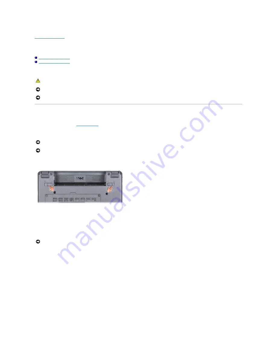
Turn the computer over.  


3.

Remove the two screws from the base of the computer.  


4.

Turn the computer top-side up and open the display.  


5.

Carefully lift the keyboard and hold it to access the keyboard connector.  


6.

Push out the securing tabs that secure the keyboard cable to the system board and remove the keyboard.  


CAUTION: 

Before working inside your computer, read the safety information that shipped with your computer. For additional safety best 

practices information, see the Regulatory Compliance Homepage at www.dell.com/regulatory_compliance.


NOTICE: 

To avoid electrostatic discharge, ground yourself by using a wrist grounding strap or by periodically touching an unpainted metal surface (such 

as a connector on the back of the computer).


NOTICE: 

To help prevent damage to the system board, you must remove the battery from the battery bay before you begin working inside the 

computer.


NOTICE: 

The keycaps on the keyboard are fragile, easily dislodged, and time-consuming to replace. Be careful when removing and handling the 

keyboard.


NOTICE: 

Be extremely careful when removing and handling the keyboard. Failure to do so could result in scratching the display panel.


NOTICE: 

The securing tabs that secure the keyboard cable to the system board are fragile. To avoid damage to the securing tabs, do not push them 

too far.

Summary of Contents for Inspiron Mini 9 910

Page 1: ...her trademarks and trade names may be used in this document to refer to either the entities claiming the marks and names or their products Dell Inc disclaims any proprietary interest in trademarks and trade names other than its own Model PP39S August 2008 Rev A00 Before You Begin Module Cover Memory Module Solid state Drive Communication Cards Keyboard Palm Rest Internal Card With Bluetooth Wirele...

Page 2: ...ttery lock latch to the lock position Back to Contents Page CAUTION Before working inside your computer read the safety information that shipped with your computer For additional safety best practices information see the Regulatory Compliance Homepage at www dell com regulatory_compliance CAUTION Before performing this procedure turn off the computer disconnect the AC adapter from the electrical o...

Page 3: ... turns off Before Working Inside Your Computer Use the following safety guidelines to help protect your computer from potential damage and to help to ensure your own personal safety NOTE Flash BIOS update program CD ships only in certain countries when you replace the system board NOTICE To avoid losing data save and close all open files and exit all open programs before you turn off your computer...

Page 4: ...y lock latch towards the outer edges 9 Slide the battery out of the battery bay 10 Turn the computer top side up open the display and press the power button to ground the system board Back to Contents Page NOTICE To avoid damaging the computer perform the following steps before you begin working inside the computer NOTICE To disconnect a network cable first unplug the cable from your computer and ...

Page 5: ...P 1 Ensure that the AC adapter is plugged in the main battery is properly installed and a network cable is attached 2 Turn on the computer 3 Locate the latest BIOS update file for your computer at support dell com 4 Click Download Now to download the file 5 If the Export Compliance Disclaimer window appears click Yes I Accept this Agreement The File Download window appears 6 Click Save this progra...

Page 6: ...o disk and then click OK The Save In window appears 9 Click the down arrow to view the Save In menu select Documents BIOS and then click Save 10 Click Close if the Download Complete window appears 11 Open the terminal command line application and proceed as follows a Type sudo s b Type your password c Type cd Documents d Type cd BIOS e Type 910A00 flash start string appears The computer will resta...

Page 7: ...palm rest 7 Lift the card out of the palm rest Replacing the Card 1 Insert card into the slot and tighten the two screws 2 Turn the palm rest over 3 Replace the palm rest see Replacing the Palm Rest 4 Replace the keyboard see Replacing the Keyboard CAUTION Before working inside your computer read the safety information that shipped with your computer For additional safety best practices informatio...

Page 8: ... Replace the module cover see Replacing the Module Cover 6 Slide the battery into the battery bay until it clicks in place and slide the battery lock latch towards the lock position Back to Contents Page ...

Page 9: ...display bezel see Replacing the Display Bezel 4 Replace the display assembly see Replacing the Display Assembly 5 Replace the palm rest see Replacing the Palm Rest 6 Replace the keyboard see Replacing the Keyboard 7 Replace the module cover see Replacing the Module Cover 8 Slide the battery into the battery bay until it clicks in place and slide the battery lock latch towards the lock position CAU...

Page 10: ...Back to Contents Page ...

Page 11: ...d hold the coin cell battery in place 3 Replace the system board see Replacing the System Board 4 Replace the display assembly see Replacing the Display Assembly 5 Replace the palm rest see Replacing the Palm Rest 6 Replace the keyboard see Replacing the Keyboard 7 Replace the module cover see Replacing the Module Cover CAUTION Before working inside your computer read the safety information that s...

Page 12: ...8 Slide the main battery into the battery bay until it clicks in place and slide the battery lock latch towards the lock position Back to Contents Page ...

Page 13: ...r routing guides 6 Pull the Mini Card antenna cables through the system board as shown in the figure CAUTION Before working inside your computer read the safety information that shipped with your computer For additional safety best practices information see the Regulatory Compliance Homepage at www dell com regulatory_compliance NOTICE To avoid electrostatic discharge ground yourself by using a wr...

Page 14: ...tighten the two display assembly hinge screws 3 Carefully route the display cables and the speaker cable into their routing guides and connect them to the respective system board connectors 4 Carefully slide the Mini Card antenna cables through the system board and into their routing guides 5 Replace the palm rest see Replacing the Palm Rest 6 Replace the keyboard see Replacing the Keyboard 7 Repl...

Page 15: ...e display bezel over the display panel and gently snap into place 2 Follow the instructions in Replacing the Display Assembly Display Panel Removing the Display Panel 1 Follow the instructions Display Assembly 2 Remove the display bezel see Display Bezel 3 Remove the camera see Removing the Camera NOTICE The display bezel is extremely fragile Be careful when removing it to prevent damaging the bez...

Page 16: ... the display bracket to the display panel by replacing the two screws on each side of the display panel 2 Align the display panel with the display cover and replace the six screws 3 Replace the camera see Replacing the Camera 4 Replace the display bezel see Replacing the Display Bezel 5 Follow the instructions in Replacing the Display Assembly 1 display cover 2 display panel 3 screw 6 1 screw 4 to...

Page 17: ...d disconnect the flex cable Replacing the Display Panel Cable 1 Connect the flex cable to the display board connector and secure it with the conductive tape 2 Replace the display panel see Replacing the Display Panel 3 Replace the camera see Replacing the Camera 4 Replace the display bezel see Replacing the Display Bezel 5 Follow the instructions in Replacing the Display Assembly Back to Contents ...

Page 18: ...nal safety best practices information see the Regulatory Compliance Homepage at www dell com regulatory_compliance NOTICE To avoid electrostatic discharge ground yourself by using a wrist grounding strap or by periodically touching an unpainted metal surface such as a connector on the back of the computer NOTICE To help prevent damage to the system board you must remove the battery from the batter...

Page 19: ...lose the display turn the computer over 4 Replace the two screws in the base of the computer 5 Slide the battery into the battery bay until it clicks into place and slide the battery lock latch to the lock position Back to Contents Page 1 keyboard 2 keyboard tab 3 3 keyboard cable 4 securing tab 2 NOTICE The keycaps on the keyboard are fragile easily dislodged and time consuming to replace Be care...

Page 20: ...h in the memory module edge connector with the tab in the memory module connector slot 3 Slide the memory module firmly into the slot at a 45 degree angle and rotate the memory module down until it clicks into place If the module does not click into place remove the memory module and reinstall it CAUTION Before working inside your computer read the safety information that shipped with your compute...

Page 21: ...guration information To confirm the amount of memory installed in the computer Windows XP Right click the My Computer icon on your desktop then click Properties General Ubuntu Click System Administration System Monitor Back to Contents Page NOTE If the memory module is not installed properly the computer may not boot No error message indicates this failure 1 tab 2 notch NOTICE If the cover is diff...

Page 22: ...the Module Cover 5 Slide the battery into the battery bay until it clicks in place and slide the battery lock latch towards the lock position Back to Contents Page CAUTION Before working inside your computer read the safety information that shipped with your computer For additional safety best practices information see the Regulatory Compliance Homepage at www dell com regulatory_compliance NOTICE...

Page 23: ......

Page 24: ... Mini Cards l Wireless Local Area Network WLAN l Mobile Broadband or Wireless Wide Area Network WWAN CAUTION Before working inside your computer read the safety information that shipped with your computer For additional safety best practices information see the Regulatory Compliance Homepage at www dell com regulatory_compliance 1 SIM 2 battery bay CAUTION Before working inside your computer read ...

Page 25: ... securing screw 2 3 antenna cable connector 2 NOTICE When the Mini Card is not in the computer store it in protective antistatic packaging See the information on protection against electrostatic discharge in the safety information that shipped with your computer NOTICE The connectors are keyed to ensure correct insertion If you feel resistance check the connectors on the card and on the system boa...

Page 26: ...dule Cover 8 Slide the battery into the battery bay until it clicks in place and slide the battery lock latch to the lock position 9 Install the drivers and utilities for your computer as required For more information see the Dell Technology Guide Back to Contents Page Connectors on the Mini Card Antenna Cable Color Scheme WWAN 2 antenna cables Main WWAN white triangle Auxiliary WWAN black triangl...

Page 27: ...e the seven screws from the top of the palm rest 7 Disconnect the Bluetooth card cable touch pad cable and the power button cable from the respective system board connectors CAUTION Before working inside your computer read the safety information that shipped with your computer For additional safety best practices information see the Regulatory Compliance Homepage at www dell com regulatory_complia...

Page 28: ...2 Align the tabs of the palm rest with the computer base 3 Gently snap the palm rest into place 4 Connect the Bluetooth card cable touch pad cable and the power button cable to the respective system board connectors 5 Replace the seven screws on the top of the palm rest 1 power button cable 2 screw 7 3 Bluetooth card cable 4 palm rest 5 touch pad cable NOTICE Carefully separate the palm rest from ...

Page 29: ...e left and right rubber bumpers 8 Replace the keyboard see Replacing the Keyboard 9 Replace the module cover see Replacing the Module Cover 10 Slide the battery into the battery bay until it clicks in place and slide the battery lock latch towards the lock position Back to Contents Page ...

Page 30: ...utton Board 1 Insert the power button board into the slot and tighten the two screws 2 Turn the palm rest over 3 Replace the palm rest see Replacing the Palm Rest 4 Replace the keyboard see Replacing the Keyboard 5 Replace the module cover see Replacing the Module Cover CAUTION Before working inside your computer read the safety information that shipped with your computer For additional safety bes...

Page 31: ...6 Slide the battery into the battery bay until it clicks in place and slide the battery lock latch towards the lock position Back to Contents Page ...

Page 32: ...les 2 Replace the three speaker screws that secure the speakers to the display base 3 Replace the display bezel see Replacing the Display Bezel 4 Replace the display assembly see Replacing the Display Assembly 5 Replace the palm rest see Replacing the Palm Rest 6 Replace the keyboard see Replacing the Keyboard 7 Replace the module cover see Replacing the Module Cover CAUTION Before working inside ...

Page 33: ...8 Slide the battery into the battery bay until it clicks in place and slide the battery lock latch towards the lock position Back to Contents Page ...

Page 34: ...er For additional safety best practices information see the Regulatory Compliance Homepage at www dell com regulatory_compliance CAUTION If you remove the solid state drive from the computer when the drive is hot do not touch the solid state drive NOTICE To prevent data loss turn off your computer see Turning Off Your Computer before removing the solid state drive Do not remove the solid state dri...

Page 35: ...ck Start Guide 7 Install the drivers and utilities for your computer as needed see Reinstalling Drivers and Utilities in your computer Setup Guide Back to Contents Page NOTICE Before turning on the computer replace all screws and ensure that no stray screws remain inside the computer Failure to do so may result in damage to the computer ...

Page 36: ...e Cover 3 Remove the memory module see Removing the Memory Module 4 Remove the solid state drive see Removing the Solid state Drive 5 Remove the keyboard see Removing the Keyboard 6 Remove the palm rest see Removing the Palm Rest 7 Disconnect the display cables Mini Card antenna cables and the speaker cable from the respective system board connectors see Display Assembly CAUTION Before working ins...

Page 37: ...oard To set the keyboard matrix according to your country see Setting the Keyboard Matrix Setting the Keyboard Matrix 1 Turn off your computer see Turning Off Your Computer 2 If your computer is connected to the AC adapter disconnect the AC adapter from the computer 3 Press and hold the following key combination for the desired keyboard matrix United States Fn S United Kingdom Fn K Japan Fn J 1 sc...

Page 38: ... Korea Fn E 4 Connect the AC adapter to the computer and then plug it into a wall outlet or surge protector 5 Release the key combination Back to Contents Page ...

Reviews: