background image

Installing the I/O board.............................................................................................................................................. 34

Touchpad.............................................................................................................................................................................35

Removing the touchpad.............................................................................................................................................35
Installing the touchpad...............................................................................................................................................36

Display assembly................................................................................................................................................................ 37

Removing the display assembly................................................................................................................................37
Installing the display assembly..................................................................................................................................39

Power-adapter port...........................................................................................................................................................41

Removing the power-adapter port.......................................................................................................................... 41
Installing the power-adapter port............................................................................................................................42

Power-button board......................................................................................................................................................... 43

Removing the power-button board.........................................................................................................................43
Installing the power-button board...........................................................................................................................44

System board..................................................................................................................................................................... 45

Removing the system board..................................................................................................................................... 45
Installing the system board....................................................................................................................................... 48

Keyboard............................................................................................................................................................................. 50

Removing the keyboard............................................................................................................................................. 50
Installing the keyboard............................................................................................................................................... 52

Palmrest...............................................................................................................................................................................53

Removing the palmrest.............................................................................................................................................. 53
Installing the palmrest................................................................................................................................................ 54

Chapter 3: Drivers and downloads............................................................................................... 56

Chapter 4: System setup............................................................................................................. 57

Entering BIOS setup program........................................................................................................................................ 57
Navigation keys..................................................................................................................................................................57
Boot Sequence...................................................................................................................................................................57
One time boot menu.........................................................................................................................................................58
System setup options.......................................................................................................................................................58
Clearing CMOS settings.................................................................................................................................................. 67
Clearing BIOS (System Setup) and System passwords...........................................................................................67

Chapter 5: Troubleshooting.........................................................................................................68

SupportAssist diagnostics...............................................................................................................................................68

Locate the Service Tag or Express Service Code of your Dell computer

 ..............................................68

System diagnostic lights..................................................................................................................................................68
Built-in self-test (BIST)................................................................................................................................................... 69
Recovering the operating system..................................................................................................................................70
Flashing the BIOS..............................................................................................................................................................70
Flashing BIOS (USB key).................................................................................................................................................70
Backup media and recovery options.............................................................................................................................70
WiFi power cycle................................................................................................................................................................ 71
Flea power release............................................................................................................................................................. 71

Chapter 6: Getting help and contacting Dell................................................................................ 72

4

Contents

Summary of Contents for Inspiron 7706

Page 1: ...Inspiron 7706 2 in 1 Service Manual Regulatory Model P98F Regulatory Type P98F001 September 2020 Rev A00 ...

Page 2: ...ential damage to hardware or loss of data and tells you how to avoid the problem WARNING A WARNING indicates a potential for property damage personal injury or death 2020 Dell Inc or its subsidiaries All rights reserved Dell EMC and other trademarks are trademarks of Dell Inc or its subsidiaries Other trademarks may be trademarks of their respective owners ...

Page 3: ...talling the battery 16 Coin cell battery 17 Removing the coin cell battery 17 Installing the coin cell battery 18 Memory module 19 Removing the memory module 19 Installing the memory module 20 Wireless card 21 Removing the wireless card 21 Installing the wireless card 21 Speakers 23 Removing the speakers 23 Installing the speakers 23 Heat sink 24 Removing the heat sink 24 Installing the heat sink ...

Page 4: ...mrest 53 Removing the palmrest 53 Installing the palmrest 54 Chapter 3 Drivers and downloads 56 Chapter 4 System setup 57 Entering BIOS setup program 57 Navigation keys 57 Boot Sequence 57 One time boot menu 58 System setup options 58 Clearing CMOS settings 67 Clearing BIOS System Setup and System passwords 67 Chapter 5 Troubleshooting 68 SupportAssist diagnostics 68 Locate the Service Tag or Expr...

Page 5: ...tory_compliance WARNING Disconnect your computer from all power sources before opening the computer cover or panels After you finish working inside the computer replace all covers panels and screws before connecting your computer to an electrical outlet CAUTION To avoid damaging the computer ensure that the work surface is flat dry and clean CAUTION To avoid damaging the components and cards handl...

Page 6: ...nti static straps is no longer allowed they do not provide adequate protection Touching the chassis before handling parts does not ensure adequate ESD protection on parts with increased sensitivity to ESD damage Handle all static sensitive components in a static safe area If possible use anti static floor pads and workbench pads When unpacking a static sensitive component from its shipping carton ...

Page 7: ...lded bags are preferred However you should always return the damaged part using the same ESD bag and packaging that the new part arrived in The ESD bag should be folded over and taped shut and all the same foam packing material should be used in the original box that the new part arrived in ESD sensitive devices should be removed from packaging only at an ESD protected work surface and parts shoul...

Page 8: ... have magnetic surfaces Ensure that the screws are not left attached to such surfaces when replacing a component NOTE Screw color may vary with the configuration ordered Table 1 Screw list Component Secured to Screw type Quantity Screw image Base cover Palm rest and keyboard assembly M2x4 8 Base cover Palm rest and keyboard assembly M2x8 3 Battery Palm rest and keyboard assembly M2x3 5 2 Battery P...

Page 9: ...board assembly M2 5x3 6 Power button board Palm rest and keyboard assembly M2x3 2 Power button bracket Palm rest and keyboard assembly M2x3 5 2 Power adapter port Palm rest and keyboard assembly M2x3 5 1 USB Type C bracket Palm rest and keyboard assembly M2x3 5 2 System board Palm rest and keyboard assembly M2x2 1 System board Palm rest and keyboard assembly M2x3 5 1 Major components of Inspiron 7...

Page 10: ...1 Base cover 2 Solid state drive thermal bracket 3 Solid state drive 4 Memory modules 10 Removing and installing components ...

Page 11: ... 24 Power button bracket NOTE Dell provides a list of components and their part numbers for the original system configuration purchased These parts are available according to warranty coverages purchased by the customer Contact your Dell sales representative for purchase options Base cover Removing the base cover 1 Follow the procedure in Before working inside your computer The following images in...

Page 12: ...12 Removing and installing components ...

Page 13: ...he hinges are located doing so may damage the base cover NOTE Upon loosening the three captive screws M2x8 the base cover will pop up creating a gap between the base cover and the palm rest assembly 3 Lift the base cover use a plastic scribe for gentle prying of the cover if necessary 4 Disconnect the battery cable from the system board 5 Turn your computer over and press the power button for 15 s...

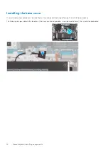
Page 14: ... component remove the existing component before performing the installation procedure The following images indicate the location of the base cover and provide a visual representation of the installation procedure 14 Removing and installing components ...

Page 15: ...e your computer Battery Lithium ion battery precautions CAUTION Exercise caution when handling Lithium ion batteries Discharge the battery completely before removing it Disconnect the AC power adapter from the system and operate the computer solely on battery power the battery is fully discharged when the computer no longer turns on when the power button is pressed Do not crush drop mutilate or pe...

Page 16: ...ve the base cover The following image indicates the location of the battery and provides a visual representation of the removal procedure 1 Disconnect the battery cable from the system board applicable only if not disconnected earlier 2 Remove the captive screw that secures the battery to the palm rest and keyboard assembly 3 Remove the two screws M2x3 5 that secure the battery to the palm rest an...

Page 17: ...low the procedure in After working inside your computer Coin cell battery Removing the coin cell battery 1 Follow the procedure in Before working inside your computer NOTE Removing the I O board cable is equivalent to removing the coin cell battery It resets the settings of the BIOS setup program to default It is recommended that you note down the settings of the BIOS setup program before removing...

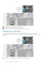
Page 18: ...embly Installing the coin cell battery If you are replacing a component remove the existing component before performing the installation procedure The following image indicates the location of the coin cell battery and provides a visual representation of the installation procedure 1 Adhere the coin cell battery to the slot on the palm rest and keyboard assembly 18 Removing and installing component...

Page 19: ...procedure in Before working inside your computer 2 Remove the base cover The following image indicates the location of the memory modules and provides a visual representation of the removal procedure 1 Lift the flap to access the memory module 2 Use your fingertips to carefully spread apart the securing clips on each end of the memory module slot until the memory module pops up 3 Slide and remove ...

Page 20: ... procedure 1 Lift the flap to access the memory module slot 2 Align the notch on the memory module with the tab on the memory module slot 3 Slide the memory module firmly at an angle into the memory module slot 4 Press the memory module down until it clicks into place NOTE If you do not hear the click remove the memory module and reinstall it NOTE Repeat the steps to install any other memory modul...

Page 21: ...o the wireless card and system board 2 Remove the wireless card bracket from the wireless card 3 Disconnect the antenna cables from the wireless card 4 Slide and remove the wireless card from the wireless card slot Installing the wireless card If you are replacing a component remove the existing component before performing the installation procedure The following image indicates the location of th...

Page 22: ...lack 2 Align the notch on the wireless card with the tab on the wireless card slot and insert the wireless card at an angle into the wireless card slot 3 Align the screw hole on the wireless card bracket with the screw hole on the wireless card and palm rest and keyboard assembly 4 Replace the screw M2x3 5 that secures the wireless card bracket to the wireless card and system board 1 Install the b...

Page 23: ...e the speaker cable routing and remove the speaker cable from the routing guides on the palm rest and keyboard assembly 3 Lift the speakers along with the cables off the palm rest and keyboard assembly Installing the speakers If you are replacing a component remove the existing component before performing the installation procedure The following image indicates the location of the speakers and pro...

Page 24: ...he heat sink 1 Follow the procedure in Before working inside your computer CAUTION For maximum cooling of the processor do not touch the heat transfer areas on the heat sink The oils in your skin can reduce the heat transfer capability of the thermal grease NOTE The heat sink may become hot during normal operation Allow sufficient time for the heat sink to cool before you touch it 2 Remove the bas...

Page 25: ...omponent before performing the installation procedure CAUTION Incorrect alignment of the heat sink can damage the system board and processor NOTE If either the system board or the heat sink is replaced use the thermal pad paste provided in the kit to ensure that thermal conductivity is achieved The following image indicates the location of the heat sink and provides a visual representation of the ...

Page 26: ...the heat sink to the system board 1 Install the base cover 2 Follow the procedure in After working inside your computer Fan Removing the fan 1 Follow the procedure in Before working inside your computer 2 Remove the base cover The following image indicates the location of the fan and provides a visual representation of the removal procedure 26 Removing and installing components ...

Page 27: ...n off the palm rest and keyboard assembly Installing the fan If you are replacing a component remove the existing component before performing the installation procedure The following image indicates the location of the fan and provides a visual representation of the installation procedure 1 Using the alignment posts place the fan on the palm rest and keyboard assembly Removing and installing compo...

Page 28: ...nside your computer 2 Remove the base cover The following image indicates the location of the solid state drive and provides a visual representation of the removal procedure 1 Remove the screw M2x3 5 that secure the solid state drive thermal bracket to the palm rest and keyboard assembly 2 Lift the solid state drive thermal bracket off the palm rest and keyboard assembly 3 Remove the screw M2x3 5 ...

Page 29: ...lid state drive is removed first Refer to the procedure for removing the M 2 2280 solid state drive The following image indicate where to install the solid state drive screw mount based on form factor This computer supports two solid state drive form factors M 2 2230 M 2 2280 The following image indicates the location of the M 2 2230 solid state drive and provides a visual representation of the in...

Page 30: ...ive slot 6 Slide the solid state drive firmly into the solid state drive slot at an angle 7 Replace the screw M2x3 5 that secures the solid state drive to the solid state drive bracket 8 Align the screw hole on the solid state drive thermal bracket with the screw hole on the palm rest and keyboard assembly 9 Replace the screw M2x3 5 that secures the solid state drive thermal bracket to the palm re...

Page 31: ...rive from the solid state drive slot Installing the M 2 2280 solid state drive If you are replacing a component remove the existing component before performing the installation procedure If you are replacing a M 2 2230 solid state drive with a M 2 2380 solid state drive ensure the M 2 2230 solid state drive is removed first Refer to the procedure for removing the M 2 2230 solid state drive The fol...

Page 32: ...olid state drive form factors M 2 2230 M 2 2280 The following image indicates the location of the M 2 2280 solid state drive and provides a visual representation of the installation procedure 32 Removing and installing components ...

Page 33: ...ive bracket to the palm rest and keyboard assembly 5 Align the notch on the solid state drive with the tab on the solid state drive slot 6 Slide the solid state drive firmly into the solid state drive slot at an angle 7 Replace the screw M2x3 5 that secures the solid state drive to the solid state drive bracket 8 Align the screw hole on the solid state drive thermal bracket with the screw hole on ...

Page 34: ...O board 4 Open the latch and disconnect the I O board cable from the I O board 5 Open the latch and disconnect the fingerprint reader cable from the I O board 6 Disconnect the coin cell battery cable from the I O board 7 Remove the screw M2x3 5 that secures the I O board to the palm rest and keyboard assembly 8 Slide and lift the I O board off the palm rest and keyboard assembly Installing the I O...

Page 35: ... reader cable to the connector on the I O board and close the latch to secure the cable 7 Connect the coin cell battery cable to the I O board 8 Close the left display hinge 9 Replace the three screws M2 5x4 5 that secure the left display hinge to the palm rest and keyboard assembly 1 Install the base cover 2 Follow the procedure in After working inside your computer Touchpad Removing the touchpad...

Page 36: ...t and keyboard assembly 5 Remove the five screws M2x2 that secure the touchpad to the palm rest and keyboard assembly 6 Slide and lift the touchpad along with the cable off the palm rest and keyboard assembly Installing the touchpad If you are replacing a component remove the existing component before performing the installation procedure The following image indicates the location of the touchpad ...

Page 37: ...ad bracket into the slot on the palm rest and keyboard assembly 6 Replace the three screws M2x3 5 that secure the touchpad bracket to the palm rest and keyboard assembly 1 Install the battery 2 Install the base cover 3 Follow the procedure in After working inside your computer Display assembly Removing the display assembly 1 Follow the procedure in Before working inside your computer 2 Remove the ...

Page 38: ...38 Removing and installing components ...

Page 39: ...the palm rest and keyboard assembly 4 Remove the three screws M2 5x4 5 that secure the right display hinge to the palm rest and keyboard assembly 5 Lift at an angle and slide the display assembly off the palm rest and keyboard assembly Installing the display assembly If you are replacing a component remove the existing component before performing the installation procedure Removing and installing ...

Page 40: ...The following image indicates the location of the display assembly and provides a visual representation of the installation procedure 40 Removing and installing components ...

Page 41: ... hinge to the palm rest and keyboard assembly 5 Connect the display cable connector to the system board 6 Adhere the tape that secures the display cable to the system board 1 Install the base cover 2 Follow the procedure in After working inside your computer Power adapter port Removing the power adapter port 1 Follow the procedure in Before working inside your computer 2 Remove the base cover The ...

Page 42: ...4 Disconnect the power adapter port cable from the system board 5 Lift the power adapter port along with its cable off the palm rest and keyboard assembly Installing the power adapter port If you are replacing a component remove the existing component before performing the installation procedure The following image indicates the location of the power adapter port and provides a visual representati...

Page 43: ...4 5 that secure the right display hinge to the palm rest and keyboard assembly 1 Install the base cover 2 Follow the procedure in After working inside your computer Power button board Removing the power button board 1 Follow the procedure in Before working inside your computer 2 Remove the base cover 3 Remove the fan 4 Remove the I O board The following image indicates the location of the power bu...

Page 44: ...d keyboard assembly 4 Lift the power button board along with its cable off the slot on the palm rest and keyboard assembly Installing the power button board If you are replacing a component remove the existing component before performing the installation procedure The following image indicates the location of the power button board and provides a visual representation of the installation procedure...

Page 45: ...yboard assembly 1 Install the I O board 2 Install the fan 3 Install the base cover 4 Follow the procedure in After working inside your computer System board Removing the system board 1 Follow the procedure in Before working inside your computer 2 Remove the base cover 3 Remove the memory modules 4 Remove the M 2 2230 solid state drive or M 2 2280 solid state drive as applicable 5 Remove the displa...

Page 46: ...able 3 Fan cable 4 I O board cable 5 Speaker cable 6 Touchpad cable 7 Keyboard cable 8 USB Type C port bracket The following image indicates the location of the system board and provides a visual representation of the removal procedure 46 Removing and installing components ...

Page 47: ...1 Remove the three screws M2 5x4 5 that secure the right display hinge to the palm rest and keyboard assembly Removing and installing components 47 ...

Page 48: ...play cable to the system board 13 Open the latch and disconnect the display cable from the system board 14 Remove the screw M2x2 and that secures the system board to the palm rest and keyboard assembly 15 Remove the screw M2x3 5 and that secures the system board to the palm rest and keyboard assembly 16 Lift the system board off the palm rest and keyboard assembly Installing the system board If yo...

Page 49: ...1 Align and place the system board on the palm rest and keyboard assembly Removing and installing components 49 ...

Page 50: ... USB Type C port bracket to the system board 16 Adhere the tape that secures the USB Type C port bracket to the system board 17 Close the right display hinge 18 Replace the three screws M2 5x4 5 that secure the right display hinge to the system board 1 Install the heat sink 2 Install the wireless card 3 Install the display assembly 4 Install the M 2 2230 solid state drive or M 2 2280 solid state d...

Page 51: ...off the tapes that secure the cables to the palm rest and keyboard assembly 3 Peel off the tapes to access the screws 4 Remove the 42 screws M1 2x1 5 that secure the keyboard and the keyboard bracket to the palm rest and keyboard assembly 5 Lift the keyboard bracket Removing and installing components 51 ...

Page 52: ...component remove the existing component before performing the installation procedure The following image indicates the location of the palm rest and keyboard assembly and provides a visual representation of the installation procedure of the keyboard 52 Removing and installing components ...

Page 53: ...fan 7 Install the M 2 2230 solid state drive or M 2 2280 solid state drive as applicable 8 Install the heat sink 9 Install the wireless card 10 Install the memory module 11 Install the battery 12 Install the base cover 13 Follow the procedure in After working inside your computer Palmrest Removing the palmrest 1 Follow the procedure in Before working inside your computer 2 Remove the base cover 3 ...

Page 54: ...e heat sink 17 Remove the keyboard The following image shows the palmrest After performing the steps in the pre requisites you are left with the palmrest Installing the palmrest If you are replacing a component remove the existing component before performing the installation procedure The following image shows the palmrest Place the palmrest on a clean dry and flat surface 54 Removing and installi...

Page 55: ...wer adapter port 5 Install the display assembly 6 Install the I O board 7 Install the fan 8 Install the M 2 2230 solid state drive or M 2 2280 solid state drive as applicable 9 Install the heat sink 10 Install the wireless card 11 Install the memory module 12 Install the speakers 13 Install the coin cell battery 14 Install the touchpad 15 Install the battery 16 Install the base cover 17 Follow the...

Page 56: ...rivers and downloads When troubleshooting downloading or installing drivers it is recommended that you read the Dell Knowledge Based article Drivers and Downloads FAQ SLN128938 3 56 Drivers and downloads ...

Page 57: ...options changes that you make are recorded but do not take effect until you restart the system Keys Navigation Up arrow Moves to the previous field Down arrow Moves to the next field Enter Selects a value in the selected field if applicable or follow the link in the field Spacebar Expands or collapses a drop down list if applicable Tab Moves to the next focus area Esc Moves to the previous page un...

Page 58: ... may or may not be displayed Table 3 System setup options System information menu Overview BIOS Version Displays the BIOS version number Service Tag Displays the Service Tag of the computer Asset Tag Displays the Asset Tag of the computer Manufacture Date Displays the manufacture date of the computer Ownership Date Displays the ownership date of the computer Express Service Code Displays the expre...

Page 59: ...s the memory configuration of DIMM SLOT2 DEVICES Panel Type Displays the Panel Type of the computer Video Controller Displays the integrate graphics information of the computer Video Memory Displays the video memory information of the computer Wi Fi Device Displays the Wi Fi device installed in the computer Native Resolution Displays the native resolution of the computer Video BIOS Version Display...

Page 60: ...evices Date Time Date Sets the computer date in MM DD YYYY format Changes to the date take effect immediately Time Sets the computer time in HH MM SS 24 hour format You can switch between 12 hour and 24 hour clock Changes to the time take effect immediately Camera Enable Camera Enables or disables the camera By default Enable Camera is selected Audio Enables or disables all integrated audio contro...

Page 61: ...oard drives Default ON SMART Reporting Enable SMART Reporting Enables or disables Self Monitoring Analysis and Reporting Technology SMART Default OFF Drive Information Displays the information of various onboard drives Table 7 System setup options Display menu Display Display Brightness Brightness on battery power Sets the screen brightness when the computer is running on battery power Default 50 ...

Page 62: ...ndard settings for cooling fan and processor heat management This setting is a balance of performance noise and temperature USB Wake Support Wake on Dell USB C Dock Enables connecting a Dell USB C Dock to wake the computer from Standby Default ON Block Sleep Blocks the computer from entering Sleep S3 mode in the operating system Default OFF NOTE If enabled the computer will not go to sleep Intel R...

Page 63: ...oot Path Security Determines if the system will prompt the user to enter the admin password if set when booting to a UEFI boot path device frim the F12 boot menu Default Always Except Internal HDD Table 11 System setup options Passwords menu Passwords Admin Password Enables the user to set change or delete the administrator admin password The admin password enables several security features System...

Page 64: ...er from a bad BIOS image as long as the Boot Block portion is intact and functioning Default ON NOTE BIOS recovery is designed to fix the main BIOS block and cannot work if the Boot Block is damaged In addition this feature cannot work in the event of EC corruption ME corruption or a hardware issue The recovery image must exist on an unencrypted partition on the drive BIOS Downgrade Allow BIOS Dow...

Page 65: ...rols operation of function keys F1 F12 Default Lock Mode Secondary Keyboard Illumination Enables the user to change the keyboard illumination settings Default Bright Keyboard Backlight Timeout on AC Enables the user to define the timeout value for the keyboard backlight when an AC adapter is plugged into the system Default 1 minute Keyboard Backlight Timeout on Battery Enables the user to define t...

Page 66: ...ctive Cores CPU core disabling is not supported with current BIOS version Changes the number of CPU cores available to the operating system The default value is set to the maximum number of cores Default All Cores Intel SpeedStep Enable Intel SpeedStep Technology Enables or disables the Intel SpeedStep Technology to dynamically adjust processor voltage and core frequency decreasing average power c...

Page 67: ...f your computer 2 Remove the base cover NOTE The battery must be disconnected from the system board see Step 4 in Removing the base cover 3 Press and hold the power button for 15 seconds to drain the flea power 4 Before you turn on your computer follow the steps in Installing the base cover 5 Turn on your computer Clearing BIOS System Setup and System passwords To clear the system or BIOS password...

Page 68: ...rvice Tag or Express Service Code To view relevant support resources for your Dell computer we recommend entering the Service Tag or Express Service Code at www dell com support For more information on how to find the Service Tag for your computer see Locate the Service Tag for your Dell Laptop System diagnostic lights Battery status light Indicates the power and battery charge status Solid white ...

Page 69: ...eds a replacement 1 M Bist M BIST is the system board built in self test diagnostics tool that improves the diagnostics accuracy of system board embedded controller EC failures M BIST must be manually initiated before POST and can also run on a dead system 2 L BIST L BIST is an enhancement to the single LED error code diagnostics and is automatically initiated during POST 3 LCD BIST LCD BIST is an...

Page 70: ...tect feature or manually browse for your computer model 4 Click Drivers downloads Find it myself 5 Select the operating system installed on your computer 6 Scroll down the page and expand BIOS 7 Click Download to download the latest version of the BIOS for your computer 8 After the download is complete navigate to the folder where you saved the BIOS update file 9 Double click the BIOS update file ...

Page 71: ...ss router 6 Turn on the modem 7 Turn on your computer Flea power release Flea power is the residual static electricity that remains on the computer even after it has been powered off and the battery has been disconnected from the system board The following procedure provides the instructions on how to release the flea power 1 Turn off your computer 2 Remove the base cover NOTE The battery cable mu...

Page 72: ...odel number and then click or tap the search icon to view the related articles Learn and know the following information about your product Product specifications Operating system Setting up and using your product Data backup Troubleshooting and diagnostics Factory and system restore BIOS information See Me and My Dell at www dell com support manuals To locate the Me and My Dell relevant to your pr...

Reviews: