background image

Identifier

GUID-69332260-F504-4C70-A535-1E11124CC185

Status

Released

Replacing the heat sink

WARNING: 

Before working inside your computer, read the safety information that shipped with your computer and follow the 

steps in 

Before working inside your computer

. After working inside your computer, follow the instructions in 

After working inside 

your computer

. For more safety best practices, see the Regulatory Compliance home page a

www.dell.com/

regulatory_compliance

.

CAUTION: 

Incorrect alignment of the heat sink can damage the system board and processor.

NOTE: 

If either the system board or the heat sink is replaced, use the thermal pad provided in the kit to ensure that thermal 

conductivity is achieved.

Identifier

GUID-CC215BED-BB13-4D5D-BE24-53678B2F76F6

Status

Released

Procedure

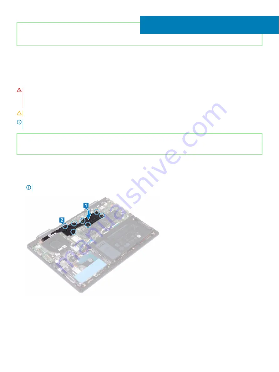
Align the screw holes on the heat sink with the screw holes on the system board.

In sequential order (as indicated on the heat-sink), tighten the seven captive screws that secure the heat sink to the system board.

NOTE: 

The number of screws may vary depending on the configuration ordered.

19

Replacing the heat sink

37

Summary of Contents for Inspiron 5482

Page 1: ...Inspiron 5482 Service Manual Computer Model Inspiron 5482 Regulatory Model P93G Regulatory Type P93G001 ...

Page 2: ...amage to hardware or loss of data and tells you how to avoid the problem WARNING A WARNING indicates a potential for property damage personal injury or death Identifier GUID 089FFA4B 3A62 4B51 BDE1 309C58A451D9 Status Released 2018 Dell Inc or its subsidiaries All rights reserved Dell EMC and other trademarks are trademarks of Dell Inc or its subsidiaries Other trademarks may be trademarks of thei...

Page 3: ... Lifting equipment 11 4 Recommended tools 12 5 Screw list 13 6 Removing the base cover 14 Procedure 14 7 Replacing the base cover 16 Procedure 16 8 Removing the battery 18 Prerequisites 18 Procedure 18 9 Replacing the battery 20 Procedure 20 Post requisites 21 10 Removing the coin cell battery 22 Procedure 22 11 Replacing the coin cell battery 23 Procedure 23 12 Removing the memory modules 24 Prer...

Page 4: ...ost requisites 34 18 Removing the heat sink 35 Prerequisites 35 Procedure 35 19 Replacing the heat sink 37 Procedure 37 Post requisites 38 20 Removing the fan 39 Prerequisites 39 Procedure 39 21 Replacing the fan 40 Procedure 40 Post requisites 40 22 Removing the speakers 41 Prerequisites 41 Procedure 41 23 Replacing the speakers 42 Procedure 42 Post requisites 42 24 Removing the I O board 43 Prer...

Page 5: ...s 51 Procedure 51 31 Replacing the display assembly 53 Procedure 53 Post requisites 54 32 Removing the power button with fingerprint reader 55 Prerequisites 55 Procedure 55 33 Replacing the power button with fingerprint reader 57 Procedure 57 Post requisites 58 34 Removing the system board 59 Prerequisites 59 Procedure 59 35 Replacing the system board 62 Procedure 62 Post requisites 64 36 Removing...

Page 6: ...luetooth drivers 74 41 System setup 75 Boot Sequence 75 Navigation keys 75 BIOS overview 76 Entering BIOS setup program 76 System setup options 76 Clearing CMOS settings 81 Clearing BIOS System Setup and System passwords 81 42 Troubleshooting 83 Flashing the BIOS 83 Flashing BIOS USB key 83 Enhanced Pre Boot System Assessment ePSA diagnostics 84 Running the ePSA diagnostics 84 Diagnostics 84 Enabl...

Page 7: ... files and exit all open applications 2 Shut down your computer Click Start Power Shut down NOTE If you are using a different operating system see the documentation of your operating system for shut down instructions 3 Disconnect your computer and all attached devices from their electrical outlets 4 Disconnect all attached network devices and peripherals such as keyboard mouse and monitor from you...

Page 8: ... all screws and ensure that no stray screws remain inside your computer 2 Connect any external devices peripherals or cables you removed before working on your computer 3 Replace any media cards discs or any other parts that you removed before working on your computer 4 Connect your computer and all attached devices to their electrical outlets 5 Turn on your computer 2 8 After working inside your ...

Page 9: ... you must disengage before disconnecting the cable When disconnecting cables keep them evenly aligned to avoid bending any connector pins When connecting cables ensure that the ports and connectors are correctly oriented and aligned CAUTION Press and eject any installed card from the media card reader Identifier GUID E1EAA29F F785 45A4 A7F8 3E717B40D541 Status Released Electrostatic discharge ESD ...

Page 10: ...t and bonding wire Never use wireless wrist straps Always be aware that the internal wires of a wrist strap are prone to damage from normal wear and tear and must be checked regularly with a wrist strap tester in order to avoid accidental ESD hardware damage It is recommended to test the wrist strap and bonding wire at least once per week ESD Wrist Strap Tester The wires inside of an ESD strap are...

Page 11: ...rting ESD sensitive components such as replacement parts or parts to be returned to Dell it is critical to place these parts in anti static bags for safe transport Lifting equipment Adhere to the following guidelines when lifting heavy weight equipment CAUTION Do not lift greater than 50 pounds Always obtain additional resources or use a mechanical lifting device 1 Get a firm balanced footing Keep...

Page 12: ... EA979CC8 84EC 4827 86C4 C80A8C31F4BF Status Released Recommended tools The procedures in this document may require the following tools Philips screwdriver 1 Flat head screwdriver Plastic scribe 4 12 Recommended tools ...

Page 13: ...m rest and keyboard assembly M2x3 1 I O board Palm rest and keyboard assembly M2x3 2 Fan Palm rest and keyboard assembly M2x3 2 Wireless card System board M2x3 1 Power adapter port Palm rest and keyboard assembly M2x3 1 Power button Palm rest and keyboard assembly M2x3 2 USB Type C bracket System board M2x3 2 System board Palm rest and keyboard assembly M2x2 Big Head 6 Touchpad bracket Palm rest a...

Page 14: ...ty best practices see the Regulatory Compliance home page at www dell com regulatory_compliance Identifier GUID E98A57DE E602 4D42 AC30 97681E32572B Status Released Procedure 1 Remove the six screws M2x6 that secure the base cover to the palm rest and keyboard assembly 2 Loosen the three captive screws that secure the base cover to the palm rest and keyboard assembly 3 Using your fingertips pry th...

Page 15: ...l the tape that secures the battery cable to the battery cable connector 7 Disconnect the battery cable from the system board 8 Turn the computer over open the display then press and hold the power button for 15 seconds to ground the system board Removing the base cover 15 ...

Page 16: ...fety best practices see the Regulatory Compliance home page at www dell com regulatory_compliance Identifier GUID 07A09BBD DBB9 4E77 8DBC 9377FF71E45C Status Released Procedure 1 Close the display and turn the computer over Connect the battery cable to the system board 2 Adhere the tape that secures the battery cable to the battery cable connector 3 Adhere the tape that secures the battery cable t...

Page 17: ...he three captive screws that secure the base cover to the palm rest and keyboard assembly 6 Replace the six screws M2x6 that secure the base cover to the palm rest and keyboard assembly Replacing the base cover 17 ...

Page 18: ...side your computer For more safety best practices see the Regulatory Compliance home page at www dell com regulatory_compliance Identifier GUID 0C370AA3 39CD 418F B0C0 9747ADD48E61 Status Released Prerequisites Remove the base cover Identifier GUID 1AB92B2D 03AD 4C22 A9EE B12F78094F9D Status Released Procedure 1 Peel off the tape that secures the battery cable to the battery 2 Peel the tape that s...

Page 19: ...4 Remove the four screws M2x3 that secure the battery to the palm rest and keyboard assembly 5 Lift the battery off the palm rest and keyboard assembly Removing the battery 19 ...

Page 20: ...actices see the Regulatory Compliance home page at www dell com regulatory_compliance Identifier GUID A532206D 13F6 4CF0 8AAD 1AB86E79ADD3 Status Released Procedure 1 Align the screw holes on the battery with the screw holes on the palm rest and keyboard assembly 2 Replace the four screws M2x3 that secure the battery to the palm rest and keyboard assembly 3 Connect the battery cable to the system ...

Page 21: ...Identifier GUID EE31644C 8CF0 4069 89C9 C081096D205E Status Released Post requisites Replace the base cover Replacing the battery 21 ...

Page 22: ...atory Compliance home page at www dell com regulatory_compliance CAUTION Removing the coin cell battery resets the BIOS setup program s settings to default It is recommended that you note the BIOS setup program s settings before removing the coin cell battery Identifier GUID 60AEABD3 77A9 475A 98AD D2179A07C951 Status Released Procedure 1 Disconnect the coin cell battery cable from the system boar...

Page 23: ...he instructions in After working inside your computer For more safety best practices see the Regulatory Compliance home page at www dell com regulatory_compliance Identifier GUID 773172E0 F977 4843 8F6E 6AC2917F9C9D Status Released Procedure 1 Adhere the coin cell battery to the palm rest and keyboard assembly 2 Route the coin cell battery cable through the routing guides on the palm rest and keyb...

Page 24: ...es see the Regulatory Compliance home page at www dell com regulatory_compliance Identifier GUID 0C370AA3 39CD 418F B0C0 9747ADD48E61 Status Released Prerequisites Remove the base cover Identifier GUID BEF12B85 14DA 4A57 BA9A 407178F5E85A Status Released Procedure 1 Locate the memory module on the system board and lift the mylar that covers the memory modules 2 Use your fingertips to carefully spr...

Page 25: ...Removing the memory modules 25 ...

Page 26: ... best practices see the Regulatory Compliance home page at www dell com regulatory_compliance Identifier GUID B9B09D3B 06CB 4FC4 949F 1F21A58D8CBE Status Released Procedure 1 Locate the memory modules on the system board and lift the mylar that covers the memory modules 2 Align the notch on the memory module with the tab on the memory module slot 3 Slide the memory module firmly into the slot at a...

Page 27: ...lease the mylar that covers the memory modules on the system board Identifier GUID EE31644C 8CF0 4069 89C9 C081096D205E Status Released Post requisites Replace the base cover Replacing the memory modules 27 ...

Page 28: ...ur computer follow the instructions in After working inside your computer For more safety best practices see the Regulatory Compliance home page at www dell com regulatory_compliance Identifier GUID E1875075 B275 40EC 988C B3128B3FED81 Status Released Prerequisites CAUTION You need to disable the Intel Optane memory before removing Intel Optane memory module from your computer For more information...

Page 29: ...ive Intel Optane memory module to the palm rest and keyboard assembly 3 Slide and remove the solid state drive Intel Optane memory module from the solid state drive Intel Optane memory module slot Removing the solid state drive Intel Optane memory module 29 ...

Page 30: ...ing the solid state drive Identifier GUID 2602721B 1198 47DB 94E8 EB3744EAC62F Status Released Procedure 1 Align the notch on the solid state drive Intel Optane memory module with the tab on the solid state drive Intel Optane memory module slot 2 Slide the solid state drive Intel Optane memory module firmly into the solid state drive Intel Optane memory module slot at an angle 3 Press the other en...

Page 31: ...ore safety best practices see the Regulatory Compliance home page at www dell com regulatory_compliance CAUTION Hard drives are fragile Exercise care when handling the hard drive CAUTION To avoid data loss do not remove the hard drive while the computer is in sleep or on state Identifier GUID 8634EF6C 5F40 4ED8 8387 8AEDF6DA2B61 Status Released Prerequisites 1 Remove the base cover 2 Remove the ba...

Page 32: ...nect the interposer from the hard drive assembly 5 Remove the four screws M3x3 that secure the hard drive bracket to the hard drive 6 Remove the hard drive bracket off the hard drive 32 Removing the hard drive ...

Page 33: ...g inside your computer follow the instructions in After working inside your computer For more safety best practices see the Regulatory Compliance home page at www dell com regulatory_compliance CAUTION Hard drives are fragile Exercise care when handling the hard drive Identifier GUID B57E1E0D A409 4FE6 9638 45E8ACAC81F4 Status Released Procedure 1 Align the screw holes on the hard drive bracket wi...

Page 34: ...the four screws M2x3 that secure the hard drive assembly to the palm rest and keyboard assembly 6 Connect the hard drive cable to the connector on the system board Identifier GUID 3BA713E2 9D49 47FC 85A0 D4A7F7BB5AB9 Status Released Post requisites 1 Replace the battery 2 Replace the base cover 34 Replacing the hard drive ...

Page 35: ...peration Allow sufficient time for the heat sink to cool before you touch it CAUTION For maximum cooling of the processor do not touch the heat transfer areas on the heat sink The oils in your skin can reduce the heat transfer capability of the thermal grease Identifier GUID 0C370AA3 39CD 418F B0C0 9747ADD48E61 Status Released Prerequisites Remove the base cover Identifier GUID 319EA3B9 9DF7 41E8 ...

Page 36: ...36 Removing the heat sink ...

Page 37: ...atory_compliance CAUTION Incorrect alignment of the heat sink can damage the system board and processor NOTE If either the system board or the heat sink is replaced use the thermal pad provided in the kit to ensure that thermal conductivity is achieved Identifier GUID CC215BED BB13 4D5D BE24 53678B2F76F6 Status Released Procedure 1 Align the screw holes on the heat sink with the screw holes on the...

Page 38: ...Identifier GUID EE31644C 8CF0 4069 89C9 C081096D205E Status Released Post requisites Replace the base cover 38 Replacing the heat sink ...

Page 39: ...tory Compliance home page at www dell com regulatory_compliance Identifier GUID 0C370AA3 39CD 418F B0C0 9747ADD48E61 Status Released Prerequisites Remove the base cover Identifier GUID 24ED1697 AF22 4221 90A0 F995398DA09D Status Released Procedure 1 Peel off the tape that secures the fan cable to the system board 2 Disconnect the fan cable from the system board 3 Peel off the tape that secures the...

Page 40: ...home page at www dell com regulatory_compliance Identifier GUID 151D28A9 0BA1 4AA0 8D3D D950B9945E74 Status Released Procedure 1 Align the screw holes on the fan with the screw holes on the palm rest and keyboard assembly 2 Replace the two screws M2x3 securing the fan to the palm rest and keyboard assembly 3 Adhere the tape that secures the I O board cable to the fan 4 Connect the fan cable to the...

Page 41: ...afety best practices see the Regulatory Compliance home page at www dell com regulatory_compliance Identifier GUID 0C370AA3 39CD 418F B0C0 9747ADD48E61 Status Released Prerequisites Remove the base cover Identifier GUID 2B4C91C7 395C 4AD7 834E 224BA2A82A95 Status Released Procedure 1 Disconnect the speaker cable from the system board 2 Note the cable routing and remove the speaker cable from the r...

Page 42: ...tory Compliance home page at www dell com regulatory_compliance Identifier GUID B2B0E8C4 F1F8 4FF1 B58E DC31481CE4AC Status Released Procedure 1 Using the alignment posts align and place the speakers on the palm rest and keyboard assembly NOTE Replace the rubber grommets if they are pushed up while replacing the speakers 2 Route the speaker cable through the routing guides on the palm rest and key...

Page 43: ... page at www dell com regulatory_compliance Identifier GUID 0C370AA3 39CD 418F B0C0 9747ADD48E61 Status Released Prerequisites Remove the base cover Identifier GUID 18B0466B 66B7 4FA0 B52B 5072418C7CA8 Status Released Procedure 1 Peel off the tape that secures the I O board cable to the I O board 2 Open the latch and disconnect the I O board cable from the I O board 3 Disconnect the fingerprint re...

Page 44: ...92 Status Released Procedure 1 Place the I O board on the palm rest and keyboard assembly and then align the screw holes on the I O board with the screw holes on the palm rest and keyboard assembly 2 Replace the two screws M2x3 that secure the I O board to the palm rest and keyboard assembly 3 Slide the fingerprint reader cable into the connector on the I O board and close the latch to secure the ...

Page 45: ...afety best practices see the Regulatory Compliance home page at www dell com regulatory_compliance Identifier GUID 0C370AA3 39CD 418F B0C0 9747ADD48E61 Status Released Prerequisites Remove the base cover Identifier GUID 2FE62435 E7EE 4E76 AF29 F1C26B35242A Status Released Procedure 1 Disconnect the power adapter port cable from the system board 2 Remove the screw M2x3 that secures the power adapte...

Page 46: ...e page at www dell com regulatory_compliance Identifier GUID AFBE4F6D 4267 44D1 AA97 773B080E2D06 Status Released Procedure 1 Place the power adapter port into the slot on the palm rest and keyboard assembly and then align the screw hole on the power adapter port with the screw hole on the palm rest and keyboard assembly 2 Replace the screw M2x3 that secures the power adapter port to the palm rest...

Page 47: ...tory Compliance home page at www dell com regulatory_compliance Identifier GUID 0C370AA3 39CD 418F B0C0 9747ADD48E61 Status Released Prerequisites Remove the base cover Identifier GUID 357702E7 FE35 4F25 83B9 AEBB8715B8C4 Status Released Procedure 1 Locate the wireless card on the system board 2 Remove the screw M2x3 that secures the wireless card bracket and wireless card to the system board 3 Li...

Page 48: ...48 Removing the wireless card ...

Page 49: ...id damage to the wireless card do not place any cables under it 1 Connect the antenna cables to the wireless card 2 Align the notch on the wireless card with the tab on the wireless card slot and slide the wireless card at an angle into the wireless card slot The following table provides the antenna cable color scheme for the wireless card supported by your computer Table 2 Antenna cable color sch...

Page 50: ...Identifier GUID EE31644C 8CF0 4069 89C9 C081096D205E Status Released Post requisites Replace the base cover 50 Replacing the wireless card ...

Page 51: ...E6F5E F0BA 474E 9DE4 51B339F81D20 Status Released Prerequisites 1 Remove the base cover 2 Remove the wireless card Identifier GUID E66EFBCB 06E8 47A1 93AA A4E9B422F375 Status Released Procedure 1 Peel off the tape that secures the fan cable to the system board 2 Disconnect the fan cable from the system board 3 Open the latch and disconnect the I O cable from the system board 4 Peel off the tape th...

Page 52: ...t and clean surface to avoid scratching the display 8 Remove the antenna cables from the routing guides on the palm rest and keyboard assembly 9 Remove the six screws M2 5x5 that secure the display assembly to the palm rest and keyboard assembly 10 Gently lift the display assembly off the palm rest and keyboard assembly 52 Removing the display assembly ...

Page 53: ...the screw holes on the palm rest and keyboard assembly 2 Replace the six screws M2 5x5 that secure the display assembly to the palm rest and keyboard assembly 3 Route the antenna cables through the routing guides on the palm rest and keyboard assembly 4 Close the display and turn the computer over 5 Connect the fan cable to the system board 6 Adhere the tape that secures the fan cable to the syste...

Page 54: ...Identifier GUID 58B6535B CB82 46EB 99E7 8E3C6C108464 Status Released Post requisites 1 Replace the wireless card 2 Replace the base cover 54 Replacing the display assembly ...

Page 55: ...rs that are shipped with fingerprint reader Identifier GUID B2A7A97E 62A3 40B0 A45E C3B93E09A4B5 Status Released Prerequisites 1 Remove the base cover 2 Remove the I O board 3 Remove the wireless card 4 Remove the display assembly Identifier GUID 1463FCF5 D9A3 41FE 9ED3 177F4F749155 Status Released Procedure 1 Remove the two screws M2x3 that secure the power button with fingerprint reader from the...

Page 56: ...56 Removing the power button with fingerprint reader ...

Page 57: ...age at www dell com regulatory_compliance NOTE Applicable only for computers that are shipped with fingerprint reader Identifier GUID 31B24856 3F3B 4C35 87CC D92A1311723F Status Released Procedure 1 Place the power button with fingerprint reader into the slot on the palm rest and keyboard assembly 2 Open the power button with fingerprint reader cable connector latch and connect the power button wi...

Page 58: ...7D 4EC8 47FB A940 4F877368D9E9 Status Released Post requisites 1 Replace the display assembly 2 Replace the wireless card 3 Replace the I O board 4 Replace the base cover 58 Replacing the power button with fingerprint reader ...

Page 59: ...hanges again after you replace the system board NOTE Before disconnecting the cables from the system board note the location of the connectors so that you can reconnect the cables correctly after you replace the system board Identifier GUID 098F2C29 6EDC 44D1 8343 8815301D49B4 Status Released Prerequisites 1 Remove the base cover 2 Remove the battery 3 Remove the memory modules 4 Remove the coin c...

Page 60: ...ect the speaker cable from the system board 9 Open the latch and disconnect the keyboard cable from the system board 10 Open the latch and disconnect the keyboard backlight cable from the system board 11 Open the latch and disconnect the touchpad cable from the system board 12 Open the latch and disconnect the hard drive cable from the system board 13 Disconnect the coin cell battery cable from th...

Page 61: ...14 Remove the six screws M2x2 that secure the system board to the palm rest and keyboard assembly 15 Lift the system board off the palm rest and keyboard assembly Removing the system board 61 ...

Page 62: ...up program You must make the appropriate changes again after you replace the system board Identifier GUID 3E31BD37 C0BB 468B 828E 98D418A9AF9B Status Released Procedure 1 Align the screw holes on the system board with the screw holes on the palm rest and keyboard assembly 2 Replace the six screws M2x2 that secure the system board to the palm rest and keyboard assembly 3 Connect the power adapter p...

Page 63: ... the system board 12 Connect the touch screen board cable to the system board 13 Slide the display cable into the connector on the system board and close the latch to secure the cable 14 Adhere the tapes that secure the display cable and touch screen board cable to their respective connectors on the system board 15 Slide the I O board cable into the connector on the system board and close the latc...

Page 64: ...equisites 1 Replace the wireless card 2 Replace the heat sink 3 Replace the fan 4 Replace the solid state drive Intel Optane memory module 5 Replace the coin cell battery 6 Replace the memory modules 7 Replace the battery 8 Replace the base cover 64 Replacing the system board ...

Page 65: ...ance Identifier GUID 700DE9D7 C060 4C5B BBD0 F827BDFE4F44 Status Released Prerequisites 1 Remove the base cover 2 Remove the battery Identifier GUID 3A17F03C 394C 4EA4 BA4C 5EC183C0904A Status Released Procedure 1 Open the latch and disconnect the touchpad cable from the system board 2 Peel the tapes that secure the touchpad to the palm rest and keyboard assembly 3 Remove the three screws M2x2 tha...

Page 66: ...6 Lift the touchpad along with the cable at an angle from under the touch pad bracket off the palm rest and keyboard assembly 66 Removing the touchpad ...

Page 67: ...compliance Identifier GUID EBE74838 9AAB 4DE2 A94F D5FC20FB53A3 Status Released Procedure 1 Align the screw holes on the touchpad with the screw holes on the palm rest and keyboard assembly 2 Replace the four screws M2x2 that secure the touchpad to the palm rest and keyboard assembly 3 Align the screw holes on the touchpad bracket with the screw holes on the touchpad 4 Replace the three screws M2x...

Page 68: ...Identifier GUID 1AEA0DB7 765D 4602 BD20 70B982BBB458 Status Released Post requisites 1 Replace the battery 2 Replace the base cover 68 Replacing the touchpad ...

Page 69: ...C Status Released Prerequisites 1 Remove the base cover 2 Remove the battery 3 Remove the memory modules 4 Remove the coin cell battery 5 Remove the solid state drive Intel Optane memory module 6 Remove the hard drive 7 Remove the heat sink 8 Remove the fan 9 Remove the I O board 10 Remove the speakers 11 Remove the power adapter port 12 Remove the wireless card 13 Remove the display assembly 14 R...

Page 70: ...70 Removing the palm rest and keyboard assembly ...

Page 71: ...fety best practices see the Regulatory Compliance home page at www dell com regulatory_compliance Identifier GUID 0068406C ADC0 45A5 B20B B2B5FC5DA965 Status Released Procedure Place the palm rest and keyboard assembly on a clean and flat surface Identifier GUID EC46BF92 43B3 4137 98DE 86948B771BF7 Status Released Post requisites 1 Replace the touchpad 2 Replace the system board 3 Replace the powe...

Page 72: ... Replace the heat sink 11 Replace the hard drive 12 Replace the solid state drive Intel Optane memory module 13 Replace the coin cell battery 14 Replace the memory modules 15 Replace the battery 16 Replace the base cover 72 Replacing the palm rest and keyboard assembly ...

Page 73: ...ed Video drivers In the Device Manager check if the video driver is installed Install the video driver update from www dell com support Identifier GUID 4DD27E61 C558 4F8F BD02 38B32A938285 Status Released Intel Serial IO driver In the Device Manager check if the Intel Serial IO driver is installed Install the driver updates from www dell com support Identifier GUID 43531ABB B77D 45B5 AFBA B90BDF78...

Page 74: ...eleased Intel Virtual Button driver In the Device Manager check if the Intel Virtual Button driver is installed Install the driver updates from www dell com support Identifier GUID 543661C6 4009 4F1B BB4F 6CF5FF28149D Status Released Wireless and Bluetooth drivers In the Device Manager check if the network card driver is installed Install the driver updates from www dell com support In the Device ...

Page 75: ...t you can boot from including the diagnostic option The boot menu options are Removable Drive if available STXXXX Drive NOTE XXX denotes the SATA drive number Optical Drive if available SATA Hard Drive if available Diagnostics NOTE Choosing Diagnostics will display the ePSA diagnostics screen The boot sequence screen also displays the option to access the System Setup screen Identifier GUID 7A7EB3...

Page 76: ... password type of hard drive installed and enabling or disabling base devices Identifier GUID 1432A924 49E9 4080 961D 2AFBDAF42039 Status Released Entering BIOS setup program 1 Turn on or restart your computer 2 During POST when the DELL logo is displayed watch for the F2 prompt to appear and then press F2 immediately NOTE The F2 prompt indicates that the keyboard is initialized This prompt can ap...

Page 77: ... Processor L2 Cache Displays the processor L2 Cache size Processor L3 Cache Displays the processor L3 Cache size HT Capable Displays whether the processor is HyperThreading HT capable 64 Bit Technology Displays whether 64 bit technology is used Device Information SATA 0 Displays the SATA 0 device information of the computer SATA 1 Displays the SATA 1 device information of the computer LOM MAC Addr...

Page 78: ...to external USB port USB PowerShare Enables or disables the USB PowerShare Audio Enables or disables the integrated audio controller Keyboard Illumination Enables you to choose the mode of the keyboard illumination feature Keyboard Backlight Timeout on AC Enables you to define the timeout value for the keyboard backlight when a power adaper is plugged Keyboard Backlight Timeout on Battery Enables ...

Page 79: ...cure Boot menu Secure Boot Secure Boot Enable Enables or disables the secure boot feature Secure Boot Mode Enables or disables the user to choose the secure boot mode Expert Key Management Enable Custom Mode Enables or disables custom mode Expert Key Management Enables or disables Expert Key Management Custom Mode Key Management Select the custom values for expert key management Table 8 System set...

Page 80: ...ings Enable adapter warnings Default Enabled Fn Lock Options Enable or disable the Fn lock mode Fastboot Enable to set the speed of the boot process Default Thorough Extend BIOS POST Time Set the BIOS POST time Full Screen Logo Enables you to display full screen logo if your image matches screen resolution Warning and Errors Enables the computer to pause when warnings and errors are detected durin...

Page 81: ...Assist System Resolution Auto OS Recovery Threshold Control the automatic boot flow for SupportAssist System Resolution Console and for the Dell OS Recovery tool SupportAssist OS Recovery Enable or disable the boot flow for the SupportAssist OS Recovery tool when certain system errors Identifier GUID CA599AD5 9996 4BE8 9643 1C626DB94E2D Status Released Clearing CMOS settings CAUTION Clearing CMOS ...

Page 82: ...NOTE For information on how to reset Windows or application passwords refer to the documentation accompanying Windows or your application 82 System setup ...

Page 83: ...or your computer 8 After the download is complete navigate to the folder where you saved the BIOS update file 9 Double click the BIOS update file icon and follow the instructions on the screen Identifier GUID 060D210F C287 462B AC38 81183D440A9D Status Released Flashing BIOS USB key 1 Follow the procedure from step 1 to step 7 in Flashing the BIOS to download the latest BIOS setup program file 2 C...

Page 84: ...ng NOTE Some tests for specific devices require user interaction Always ensure that you are present at the computer terminal when the diagnostic tests are performed For more information see Dell EPSA Diagnostic 3 0 Identifier GUID 0B893EED EFBC 4831 A9C4 7298A7A9F619 Status Released Running the ePSA diagnostics 1 Turn on your computer 2 As the computer boots press the F12 key as the Dell logo appe...

Page 85: ...ery image not found 3 4 Recovery image found but invalid Camera status light Indicates whether the camera is in use Solid white Camera is in use Off Camera is not in use Caps Lock status light Indicates whether Caps Lock is enabled or disabled Solid white Caps Lock enabled Off Caps Lock disabled Identifier GUID FE39A314 6129 4A79 A5FA B69617360582 Status Released Enabling Intel Optane memory 1 On ...

Page 86: ...rt your computer Identifier GUID B4DD52FB C0FE 4818 9D7C A0D2BF4491D7 Status Released WiFi power cycle If your computer is unable to access the internet due to WiFi connectivity issues a WiFi power cycle procedure may be performed The following procedure provides the instructions on how to conduct a WiFi power cycle NOTE Some ISPs Internet Service Providers provide a modem router combo device 1 Tu...

Page 87: ...h to retrieve the related articles Learn and know the following information about your product Product specifications Operating system Setting up and using your product Data backup Troubleshooting and diagnostics Factory and system restore BIOS information See Me and My Dell at www dell com support manuals To locate the Me and My Dell relevant to your product identify your product through one of t...

Reviews: