1.
Remove the screw from the hard drive door.
2.
Slide the drive door up until the drive assembly tabs disengage from the door slots in the bottom case assembly.
3.
Pull the drive assembly straight out of the bottom case assembly.
Replacing the Hard Drive Assembly
1.
Push the drive assembly into the hard drive opening of the computer.
2.
Align the drive assembly tabs with the bottom case assembly slots and push down until it clicks into place.
3.
Replace the screw in the drive door.
Modular Bay Devices
1.
Close the display, and turn the computer upside down on a flat work surface.
2.
Slide the modular bay latch toward the right.
3.
Keep holding the latch open while you pull the device out of the modular bay with the other hand.
Memory Module
Removing the Memory Module Cover
1.
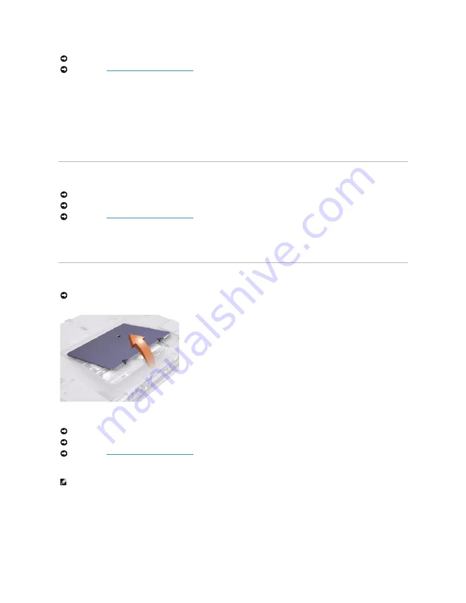
Remove the memory module cover:
a.
Use a coin or flat-blade screwdriver to release the two captive screws that secure the memory module cover.
b.
Place your finger under the cover at the indentation and lift and slide the cover open.
NOTICE:
To avoid ESD, ground yourself by using a wrist grounding strap or by touching an unpainted metal surface on the computer.
NOTICE:
Read "
Preparing to Work Inside the Computer
" before performing the following procedure.
NOTICE:
Disconnect the computer and any attached devices from electrical outlets, and remove any installed batteries.
NOTICE:
To avoid ESD, ground yourself by using a wrist grounding strap or by touching an unpainted metal surface on the computer.
NOTICE:
Read "
Preparing to Work Inside the Computer
" before performing the following procedure.
NOTICE:
The only time you should ever access the inside of your computer is when you are installing memory modules or a Mini PCI card.
NOTICE:
Disconnect the computer and any attached devices from electrical outlets, and remove any installed batteries.
NOTICE:
To avoid ESD, ground yourself by using a wrist grounding strap or by touching an unpainted metal surface on the computer.
NOTICE:
Read "
Preparing to Work Inside the Computer
" before performing the following procedure.
HINT:
The screw labeled with the "circle K" in the middle of the memory module cover secures the keyboard assembly and does not secure the memory
module cover.
Summary of Contents for Inspiron 4000
Page 42: ......


