background image

l

Attach a microphone to the 

 connector.  


l

Attach headphones or speakers to the 

 connector.  


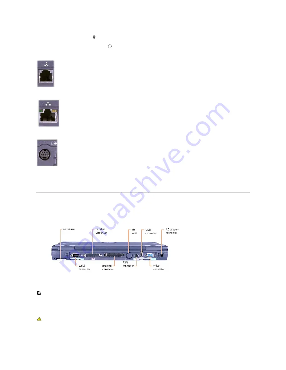
Modem Connector

Network Connector

S-Video TV-Out Connector

Fan Exhaust  

The fan works with the air intake to prevent the computer from overheating. When the computer gets hot, the small internal fan turns on and draws air 
through the air intake to cool the computer. Hot air is expelled through the fan exhaust.  

Back View  


Air Intake  

The fan works with the air intake to prevent the computer from overheating. When the computer gets hot, the small internal fan turns on and draws air 
through the air intake to cool the computer. Hot air is expelled through the fan exhaust.  

Serial Connector


If you ordered the optional internal modem, use this connector to plug in the telephone connector. 


If you ordered the optional network adapter, use this connector to connect the computer to a network. 


Use this connector to connect your computer to a television. 

HINT: 

The computer turns on the fan only when the computer gets hot. It may run most of the time or very seldom, depending on your use of the 

computer. Because the fan spins at a high rate of speed, it may make a noise. This noise is normal and does not indicate a problem with the fan or the 
computer. 


CAUTION: 

Do not push objects into or block the air intake. Doing so can cause fire or damage the interior components. Keep the opening free 

from dust and other foreign particles. 

Summary of Contents for Inspiron 4000

Page 1: ...emarks and Celeron is a trademark of Intel Corporation Microsoft and Windows are registered trademarks of Microsoft Corporation Other trademarks and trade names may be used in this document to refer to either the entities claiming the marks and names or their products Dell Computer Corporation disclaims any proprietary interest in trademarks and trade names other than its own This product incorpor...

Page 2: ...d of this procedure to complete the installation 2 Insert the Drivers and Utilities CD into the drive 3 Click the Start button and then click Run 4 Type x w2k video setup where x is the drive letter of your CD drive or DVD drive and click OK 5 Follow the instructions on your display 6 After the files are copied to your hard drive click Finish to restart your computer After installing the video dri...

Page 3: ...ers and associated utilities allow you to use and customize the integrated touch pad track stick and external mouse 1 Save and close any open files and exit any open programs because you will need to restart your computer at the end of this procedure to complete the installation 2 Insert the Drivers and Utilities CD into the drive 3 Click the Start button and then click Run 4 Type x w2k touchpad l...

Page 4: ...er 10 Click Next when the Welcome to the Windows 2000 Setup Wizard window appears 11 When the Regional Settings window appears select the settings for your locale and then click Next 12 Enter your name and organization in the Personalize Your Software window and then click Next 13 When prompted enter the Windows Product Key which is printed on the Microsoft label on your computer Then click Next 1...

Page 5: ...r display 6 After the files are copied to your hard drive click Finish to restart your computer After installing the video drivers and restarting your computer perform the following steps to set the display parameters 1 Click the Start button point to Settings and then click Control Panel 2 Double click the Display icon 3 Click the Settings tab 4 Change the Colors option to True Color 24 bit 5 Set...

Page 6: ... pad track stick and external mouse 1 Save and close any open files and exit any open programs because you will need to restart your computer at the end of this procedure to complete the installation 2 Insert the Drivers and Utilities CD into the drive 3 Click the Start button and then click Run 4 Type x win9x touchpad language setup where x is the drive letter of your CD drive or DVD drive and la...

Page 7: ...pied to your hard drive click Finish to restart your computer Installing Docking Drivers 1 If you have completed the operating system setup turn on the computer 2 Dock the computer For instructions on using the advanced port replicator APR see the Advanced Port Replicator User s Guide that came with the computer The operating system creates a hardware profile for the APR 3 To load the appropriate ...

Page 8: ...xt 14 Type the Windows Product Key in the fields provided and then click Next The Product Key is the bar code number found on the Microsoft Windows label which is located on the computer 15 When the Start Wizard appears click Finish The Enter Windows Password window appears To continue without creating a Windows user name and password click OK Otherwise type your user name and password in the appr...

Page 9: ...llow the instructions on your display 6 After the files are copied to your hard drive click Finish to restart your computer After installing the video drivers and restarting your computer perform the following steps to set the display parameters 1 Click the Start button point to Settings and then click Control Panel 2 Double click the Display icon 3 Click the Settings tab 4 Change the Colors optio...

Page 10: ...e and customize the integrated touch pad track stick and external mouse 1 Save and close any open files and exit any open programs because you will need to restart your computer at the end of this procedure to complete the installation 2 Insert the Drivers and Utilities CD into the drive 3 Click the Start button and then click Run 4 Type x winme touchpad language setup where x is the drive letter ...

Page 11: ...on and then click Run 4 Type x winme speedstp language setup where x is the drive letter of your CD drive or DVD drive and language is English French German Italian Japanese Korean Schinese Simplified Chinese Spanish or Tchinese Traditional Chinese Click OK 5 Follow the instructions on your display 6 After the files are copied to your hard drive click Finish to restart your computer Reinstalling W...

Page 12: ...n the appropriate fields and then click OK 16 If the Date Time Properties window appears adjust the date and time properties click Apply and then click OK Windows updates the system settings and restarts your computer 17 If you created a Windows user name and password type your password and click OK 18 Reinstall the appropriate drivers 19 Reenable your virus protection software Enabling Hibernate ...

Page 13: ...ety of devices including a serial mouse that require serial data transmission If you reconfigure your hardware you may need pin number and signal information for the serial connector Parallel Connector Use the 25 hole parallel connector to attach a parallel device to the computer The parallel connector is used primarily for printers The parallel connector Pin Signal I O Definition 1 DCD I Data car...

Page 14: ...ator Pin Signal I O Definition 1 STB I O Strobe 2 D0 I O Printer data bit 0 3 PD1 I O Printer data bit 1 4 PD2 I O Printer data bit 2 5 PD3 I O Printer data bit 3 6 PD4 I O Printer data bit 4 7 PD5 I O Printer data bit 5 8 PD6 I O Printer data bit 6 9 PD7 I O Printer data bit 7 10 ACK I Acknowledge 11 BUSY I Busy 12 PE I Paper end 13 SLCT I Select 14 AFD O Automatic feed 15 ERR I Error 16 INIT O I...

Page 15: ...4 SIRDY 174 SC BE1 25 D_PWRLED 75 BUSY 125 SFRAME 175 SC BE2 26 DOCK_PWR_SRC 76 PE 126 SCLKRUN 176 GND 27 DOCK_PWR_SRC 77 SLCT 127 GND 177 SAD17 28 DOCK_PWR_SRC 78 GND 128 SGNTA 178 SAD18 29 GND 79 DAT_SMB 129 SREQA 179 SAD19 30 5VDOCK 80 DCLK_SMB 130 SGNT0 180 SAD20 31 5VDOCK 81 SMB_INIT 131 SREQ0 181 SAD21 32 5VDOCK 82 GND 132 SPCIRST 182 GND 33 5VDOCK 83 DAT_DOCSM1 133 SH1SEL 183 SAD22 34 5VDOC...

Page 16: ...ta 2 KBD_DATA I Keyboard data 3 GND N A Signal ground 4 EXK_MSPWR N A External keyboard keypad mouse supply voltage 5 EXK_MSCLK I O External keyboard keypad mouse clock 6 KBD_CLK I Keyboard clock Shell N A N A Chassis ground Pin Signal Definition 1 VCC Cable power 2 Data N A 3 Data N A 4 Ground Cable ground Pin Signal I O Definition 1 RED O Red video 2 GREEN O Green video 3 BLUE O Blue video 4 DDC...

Page 17: ...levision Back to Contents Page 12 DDC_DATA I Monitor detect serial data 13 HSYNC O Horizontal synchronization 14 VSYNC O Vertical synchronization 15 DDC_CLK 1 Monitor Detect serial clock Shell N A N A Frame ground S Video Composite Video Pin Signal Pin Signal 1 GND 5 NC 2 GND 6 DCMPS L 3 DLUMA L 7 GND 4 DCRMA L ...

Page 18: ...he computer When you exit hibernate mode the programs and files that were open before you activated hibernate mode are still open Your computer enters hibernate mode if the battery charge level becomes critically low or if either the power button the power conservation key combination Fn Suspend or the display close option are programmed to activate hibernate mode in the Advanced tab of the Power ...

Page 19: ...The Low battery alarm and Critical battery alarm settings alert you with a message when the battery charge falls below a certain percentage When you receive your computer the Lower battery alarm and Critical battery alarm check boxes are selected Dell recommends that you continue to use these defaults HINT Dell recommends that you continue to use the Portable Laptop power scheme to maximize batter...

Page 20: ...urce and amount of battery charge remaining Advanced Tab The Advanced tab allows you to l Set icon and standby password options l Program the following functions Activate standby mode Activate hibernate mode Shut down Windows and turn off the computer No action None ...

Page 21: ...peedStep Tab If your computer has a Mobile Intel Pentium III processor the Power Options Properties Power Management Properties in Windows 98 window includes the Intel SpeedStep tab HINT If you are going to connect your computer to a port replicator click None when you program the display close option This setting ensures that your computer does not enter standby mode or hibernate mode when you cl...

Page 22: ...sable Intel SpeedStep technology control l Remove flag icon l Disable audio notification when performance changes Click Apply to accept any changes and then click OK to close the Intel SpeedStep technology window Back to Contents Page HINT If you disable Intel SpeedStep the processor operates at its minimum speed ...

Page 23: ...following tools l 1 magnetized Phillips screwdriver l Small flat blade screwdriver l Small plastic scribe l Microprocessor extractor l Flash BIOS update program floppy disk or CD required only when upgrading the microprocessor replacing the reserve battery or replacing the system board Preparing to Work Inside the Computer Recommended Tools Screw Identification System Components Replacing the Palm...

Page 24: ...th its corresponding hole and avoid over tightening Screw Placement Hard Drive Door Security M3 x 5 1 each Keyboard to Bottom Case Assembly M2 5 x 12 5 each LCD Display Bezel M2 5 x 5 4 each Rubber Screw Covers 4 each LCD Hinge Bracket to Bottom Case Assembly M2 5 x 5 5 each 14 1 Inch LCD Display Assembly and Flex Cable Retention Bracket to Top Cover M2 x 4 5 each Display Assembly EMI Shield Brack...

Page 25: ... device installed in the modular bay 5 Slide and hold the latch release on the right side and remove any battery installed in the battery bay 6 Locate the orange palm rest removal buttons Firmly press the buttons with the eraser end of a pencil or a dull utensil smaller than your finger to release the palm rests 7 Remove the palm rests 8 To replace the palm rests insert the tabs on the inside edge...

Page 26: ...the slots on the top of the computer 5 Press the cover along the straight edge at the back of the computer until it snaps into place 6 Firmly press the Dell logo until it snaps into place Press above both hinge covers to engage the final snaps Hard Drive Assembly Removing the Hard Drive Assembly NOTICE The hard drive is very sensitive to shock Handle the assembly by its edges do not squeeze the to...

Page 27: ... cover open NOTICE To avoid ESD ground yourself by using a wrist grounding strap or by touching an unpainted metal surface on the computer NOTICE Read Preparing to Work Inside the Computer before performing the following procedure NOTICE Disconnect the computer and any attached devices from electrical outlets and remove any installed batteries NOTICE To avoid ESD ground yourself by using a wrist g...

Page 28: ... the bottom case assembly Rotate the memory module cover down and tighten the two captive screws Mini PCI Card Assembly The optional Mini PCI card assembly may contain either a modem network adapter or combination of both You must remove the Mini PCI card subassembly before the system board assembly can be removed The Mini PCI card subassembly must be connected to the internal antenna for proper o...

Page 29: ...e screwdriver or plastic scribe into the scalloped edge next to the right Shift key and release the keyboard from the palm rest assembly NOTICE Disconnect the computer and any attached devices from electrical outlets and remove any installed batteries NOTICE To avoid ESD ground yourself by using a wrist grounding strap or by touching an unpainted metal surface on the computer NOTICE Read Preparing...

Page 30: ...talled The keys should be flush with the left and right surfaces of the palm rest 5 Reinstall the five M2 5 x 12 mm screws in the holes labeled circle K Removing the Display Assembly NOTICE Position the keyboard cable so that it does not pinch when you replace the keyboard in the bottom case assembly NOTICE Make sure that the keyboard is aligned correctly to avoid stripping the screws the next tim...

Page 31: ...MI shield bracket metal to the system board assembly 6 Remove the flex cable EMI shield retention bracket that covers the display flex cable connector on the system board 7 Pull straight up on the loop attached to the interface cable connector to disconnect the display flex cable from the system board 8 Lift the display assembly from the bottom case assembly 9 Remove the right and left plastic hin...

Page 32: ... the display flex cable to the display assembly through the flex cable retention bracket black plastic 6 Lift and rotate the top of the LCD panel out of the top cover Replacing the 14 1 Inch LCD Panel NOTICE Disconnect the computer and any attached devices from electrical outlets and remove any installed batteries NOTICE To avoid ESD ground yourself by using a wrist grounding strap or by touching ...

Page 33: ...d away to remove it from the LCD panel Display Assembly Latch 1 Remove the hard drive assembly NOTICE Disconnect the computer and any attached devices from electrical outlets and remove any installed batteries NOTICE To avoid ESD ground yourself by using a wrist grounding strap or by touching an unpainted metal surface on the computer NOTICE Read Preparing to Work Inside the Computer before perfor...

Page 34: ... Removing the Hinge Covers 1 Remove the display assembly 2 Remove the plastic hinge covers from the hinges Replacing the Hinge Covers 1 Attach the display assembly to the bottom case assembly 2 Close the display assembly and snap the hinge covers in place over the hinges Palm Rest Assembly HINT The right hinge cover is labeled R and the left hinge cover is labeled L The labels face the back of the...

Page 35: ... underneath the keyboard on the right side of the bottom case assembly next to the microprocessor thermal cooling assembly 6 Pull up on the loop attached to the palm rest flex cable connector to remove it from the interface connector on the system board assembly 7 Using the plastic scribe along the edge of the plastic remove the palm rest assembly from the bottom case assembly NOTICE Disconnect th...

Page 36: ...id cooling fan to the system board 7 Disconnect the fan power cable from the system board interface connector and remove the hybrid cooling fan NOTICE Disconnect the computer and any attached devices from electrical outlets and remove any installed batteries NOTICE To avoid ESD ground yourself by using a wrist grounding strap or by touching an unpainted metal surface on the computer NOTICE Read Pr...

Page 37: ...d remove any installed batteries NOTICE To avoid ESD ground yourself by using a wrist grounding strap or by touching an unpainted metal surface on the computer NOTICE Read Preparing to Work Inside the Computer before performing the following procedure NOTICE To ensure maximum cooling for the microprocessor do not touch the heat transfer areas on the thermal cooling assembly The oils in your skin r...

Page 38: ... Speaker Assembly NOTICE The reserve battery provides power to the computer s RTC and NVRAM when the computer is turned off Removing the battery causes the computer to lose the date and time information as well as all user specified parameters in the BIOS If possible make a copy of this information before you remove the reserve battery HINT To update or reflash the BIOS see the Dell Portable Compu...

Page 39: ...the mounting ring over the front palm rest screw post 2 Slide the speaker assembly down into the bottom case assembly System Board Assembly The system board s BIOS chip contains the system service tag number which is also visible on a bar code label on the bottom of the computer The replacement kit for the system board assembly includes a floppy disk that provides a utility for transferring the se...

Page 40: ...acing the System Board 1 Install the microprocessor on the replacement system board 2 Connect the right and left speaker to the replacement system board 3 Install the replacement system board a Insert the external microphone and headphone connectors through the plastic bottom case assembly b Replace the nine M2 5 x 5 mm screws starting on the right side of the bottom case assembly c Replace the th...

Page 41: ...e slider is inserted in its respective hole that the side of the latch with the two bumps is facing the back of the case and that the surface with the wear ribs is facing the bottom of the case 6 Snap in the new latch button from the bottom of the base making certain its snap tabs are fully engaged in the module latch 7 Ensure that the newly installed latch moves smoothly and freely when pushed an...

Page 42: ......

Page 43: ...m setup program executable file and save it to your hard drive Double click the file to open it and navigate through the example screens just as you would navigate through your actual system setup program pages The information on the right side of the screen provides details about the settings Making changes in this file will not affect your system settings It is merely a simulation of the system ...

Page 44: ...p 2 Type a word or phrase that describes your problem and then click Display 3 In the Topics Found window click the topic that describes your problem and then click Display 4 Follow the instructions shown on the screen HINT See the Tell Me How help file for information on standby mode Check the power light When the power light is on the computer has power If the power light is blinking the compute...

Page 45: ... computer or monitor If your external speaker system includes a subwoofer ensure that the subwoofer is at least 60 cm 2 ft away from the computer or external monitor Eliminate possible interference Turn off nearby fans fluorescent lights or halogen lamps to check for interference Rotate the computer to face a different direction Eliminate sunlight glare which can cause poor picture quality Restore...

Page 46: ... the printer is listed right click the printer icon click Properties and then select the Details tab 2 Ensure that the Print to the following port setting is LPT1 Printer Port Reinstall the printer driver See Installing the Printer Driver in the Dell Solutions Guide that came with your computer Verify the printer cable connections Ensure that the printer cable is connected correctly see Connecting...

Page 47: ... numeric keypad on the integrated keyboard is disabled If you connect an external USB keyboard or keypad to the computer the numeric keypad remains enabled Disconnect the keyboard cable Shut down the computer Disconnect the keyboard cable and check the cable connector for bent or broken pins Disable the numeric keypad Press the Num Lk key to disable the numeric keypad Verify that the numbers lock ...

Page 48: ...he DVD drive is not listed perform a full scan with your antivirus software to check for and remove viruses Viruses can sometimes prevent Windows from recognizing the drive Test the drive with another DVD Insert another DVD to eliminate the possibility that the original DVD is defective Clean the disc See the Tell Me How help file for instructions HINT If you must disable standby mode to write to ...

Page 49: ...n reinstall the program Window 98 SE and Windows Me 1 Click the Start button point to Settings and then click Control Panel 2 Double click the Add Remove Programs icon 3 Select the program that you want to remove 4 Click Add Remove and follow the prompts on the screen 5 See the program documentation for installation instructions Windows 2000 1 Click the Start button point to Settings and then clic...

Page 50: ...eir power sources and then from the computer 4 Remove and reinstall the battery 5 Turn on the computer If the computer does not turn on or if you cannot identify the damaged components contact Dell See Contacting Dell in the Dell Solutions Guide that came with your computer for contact information Resolving Other Technical Problems Recreating the Hibernate File Windows 98 Only When hibernate mode ...

Page 51: ...c to save your changes and exit the system setup program 8 Restart the computer 9 After the computer restarts and loads the diagnostic utility press the down arrow key to select Exit to MS DOS and then press Enter Delete the Old Hibernate File 1 Boot your computer from the Drivers and Utilities CD 2 At the R DIAGS prompt type cd and press Enter 3 At the R prompt type cd win98 suspend and press Ent...

Page 52: ... and 5 V PC Card connector size 68 pins Data width maximum PCMCIA 16 bits CardBus 32 bits Memory Architecture SDRAM Memory module socket two user accessible SODIMM sockets Memory module capacities 64 128 and 256 MB Memory type 3 3 V SODIMM Standard memory one 64 MB memory module Maximum memory 512 MB Memory clock speed 100 MHz Memory access time CL2 or CL3 CL2 and CL3 indicate a CAS latency of two...

Page 53: ...voice 72 operator Interfaces Internal ESS1920 AC97 CODEC External microphone in connector headphone speakers connector Speakers two 8 ohm speakers Internal speaker amplifier 1 0 W channel into 4 ohms Volume controls key combinations volume buttons program menus Display Type XGA active matrix color TFT Dimensions Height 214 3 mm 8 4 inches Width 285 7 mm 11 3 inches Diagonal 357 1 mm 14 1 inches Ma...

Page 54: ...ad combined ESD in accordance with IEC 801 2 Battery Type 4 cell or 8 cell smart lithium ion Dimensions Depth 88 5 mm 3 48 inches Height 21 5 mm 0 83 inch Width 139 0 mm 5 47 inches Weight 0 39 kg 0 87 lb 8 cell 0 22 kg 0 49 lb 4 cell Voltage 14 8 VDC Capacity 26 5 WHr 4 cell 53 WHr 8 cell Charge time approximate Computer off 1 hour and 6 minutes Life span approximate 500 discharge charge cycles T...

Page 55: ...torage 5 to 95 noncondensing Maximum vibration Operating 0 9 GRMS using a random vibration spectrum that simulates user environment Storage 1 3 GRMS using a random vibration spectrum that simulates air truck shipment Maximum shock Operating 152 4 cm sec 60 inches sec equal to a half sine pulse width of 2 ms Storage 203 2 cm sec 80 inches sec equal to a half sine pulse width of 2 ms Altitude Operat...

Page 56: ...keeps the display locked in place when the display is closed Display The computer has a color LCD Dell Solution Center Button Press this button to launch the Dell Solution Center where you can find support and educational tools that Dell has installed on your computer You can reprogram the button to launch a program of your choice Keyboard Status Lights ...

Page 57: ... key that supports the Windows operating systems Track Stick The track stick detects the pressure and movement of your finger for moving the cursor on the display and along with the track stick buttons provides full mouse functionality Microphone The internal microphone allows you to record voice audio Device Status Lights The green lights next to the keyboard indicate the following l The light la...

Page 58: ...drive second battery or Dell TravelLite travel module in the modular bay Display Latch Button Press the display latch button to unlock the display Battery Bay With a battery in this bay you can use the computer without plugging it into the electrical outlet Touch Pad Track Stick Buttons These buttons correspond to the left and right buttons on a standard mouse Power Button Press the power button t...

Page 59: ...Security Cable Slot This slot lets you attach a commercially available antitheft device to the computer Complete instructions for installing antitheft devices are usually included with the device Speakers Your computer has integrated speakers Right Side View NOTICE Antitheft devices are of differing designs Before you buy one make sure it works with the security cable slot in the computer ...

Page 60: ...rared sensor lets you transfer files from the computer to another infrared device without using cable connections Audio Connectors HINT The infrared sensor does not function when the computer is connected to a port replicator ...

Page 61: ...e computer Hot air is expelled through the fan exhaust Serial Connector If you ordered the optional internal modem use this connector to plug in the telephone connector If you ordered the optional network adapter use this connector to connect the computer to a network Use this connector to connect your computer to a television HINT The computer turns on the fan only when the computer gets hot It m...

Page 62: ...ch your computer to the optional advanced port replicator An advanced port replicator allows you to easily use an external keyboard mouse and monitor with your computer It also includes a network connector for connecting your computer to a network HINT The port replicator may not be available in certain countries Use this connector to attach PS 2 compatible devices such as a mouse keyboard or exte...

Page 63: ...Back to Contents Page NOTICE When you disconnect the AC adapter from the computer grasp the adapter cable connector not the cable itself and pull firmly but gently to avoid damaging the cable ...

Reviews: