background image

System Specifications

|

57

U S A   F

E D E R A L  

C

O M M U N I C A T I O N S  

C

O M M I S S I O N  

( F C C )   S

T A T E M E N T 

—  

This equipment has been tested and found to 

comply with the limits for a Class A digital device, pursuant to Part 15 of the FCC rules. These limits are designated to provide reasonable 
protection against harmful interference when the equipment is operated in a commercial environment. This equipment generates, uses, and 
can radiate radio frequency energy. If it is not installed and used in accordance to the instructions, it may cause harmful interference to radio 
communications. Operation of this equipment in a residential area is likely to cause harmful interference, in which case users will be required 
to take whatever measures necessary to correct the interference at their own expense.

Properly shielded and grounded cables and connectors must be used in order to meet FCC emission limits. Dell Force10 is not responsible for 
any radio or television interference caused by using other than recommended cables and connectors or by unauthorized changes or modifications 
in the equipment. Unauthorized changes or modification could void the user’s authority to operate the equipment.

This device complies with Part 15 of the FCC Rules. Operation is subject to the following two conditions: (1) this device may not cause 
harmful interference, and (2) this device must accept any interference received, including interference that may cause undesired operation.

  —   C

A N A D I A N  

D

E P A R T M E N T   O F  

C

O M M U N I C A T I O N  

S

T A T E M E N T    

—  

E

U R O P E A N  

U

N I O N  

E M C   D

I R E C T I V E  

C

O N F O R M A N C E  

S

T A T E M E N T 

—  

This product is in conformity with the protection requirements of EU Council Directive 2004/108/EC on the approximation of the laws of the 
Member States relating to electromagnetic compatibility. Force 10 Networks can not accept responsibility for any failure to satisfy the protection 
requirements resulting from a non-recommended modification of this product, including the fitting of non-Force10 option cards.

This product has been tested and found to comply with the limits for Class A Information Technology Equipment according to CISPR 22/
European Standard EN 55022. The limits for Class A equipment were derived for commercial and industrial environments to provide reasonable 
protection against interference with licensed communication equipment. 


CAUTION: 

This is a Class A product. In a domestic environment, this device may cause radio interference, in 

which case, the user may be required to take adequate measures.

E

U R O P E A N  

C

O M M U N I T Y  

C

O N T A C T 

—  

Dell Force10, EMEA - Central
Dahlienweg 19
66265 Heusweiler
Germany

http://www.force10networks.com/german/

Tel: +49 172 6802630 

Email: EMEA Central Sales

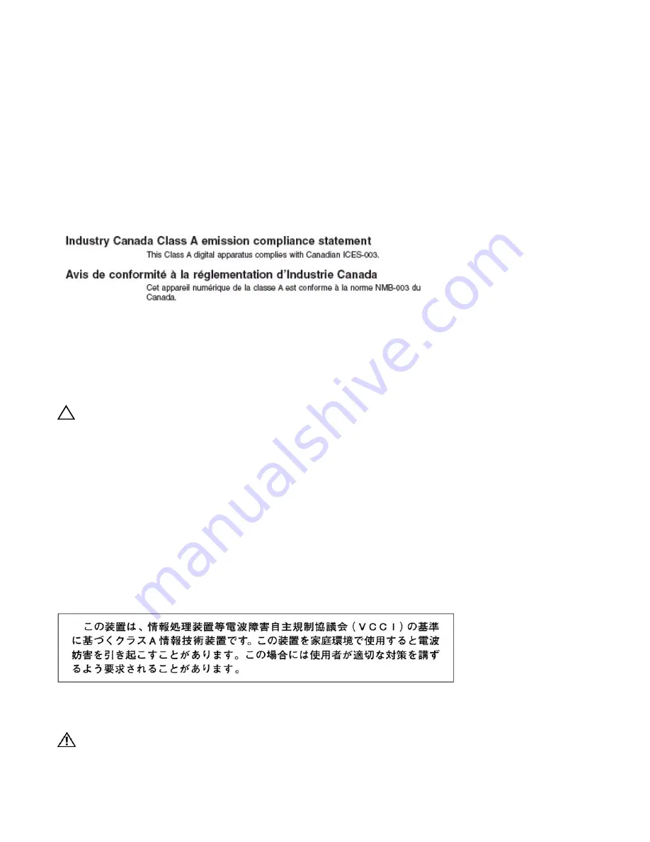
J

A P A N

:   V C C I   C

O M P L I A N C E   F O R  

C

L A S S  

A   E

Q U I P M E N T   

—  

This is Class A product based on the standard of the Voluntary Control Council For Interference by Information Technology Equipment 
(VCCI). If this equipment is used in a domestic environment, radio disturbance may arise. When such trouble occurs, the user may be required 
to take corrective actions.


WARNING: 

AC Power cords are for use with Dell Force10 equipment only, do not use Dell Force10 AC 

Power cords with any unauthorized hardware.

Summary of Contents for Force10 C150

Page 1: ...Installing and Maintaining the C150 System ...

Page 2: ...Phenom and AMD Sempron are trademarks of Advanced Micro Devices Inc Microsoft Windows Windows Server MS DOS and Windows Vista are either trademarks or registered trademarks of Microsoft Corporation in the United States and or other countries Red Hat Enterprise Linux and Enterprise Linux are registered trademarks of Red Hat Inc in the United States and or other countries Novell is a registered trad...

Page 3: ... Installing the Chassis into an Equipment Rack 14 5 RPMs and Line Cards Route Processor Modules 17 RPM Label and LEDs 17 Line Cards 18 Blank Panels 18 Installing RPMs and Line Cards 19 Removing RPMs and Line Cards 22 6 Management Cable Pinout Connecting the Console Port 23 Cable and Adapter Pin Assignments 23 Accessing the Console with a DB 9 Adapter 24 Accessing the Console with a DB 25 Adapter 2...

Page 4: ...n Tray 41 Removing and Replacing Power Supply Units 42 Removing and Replacing a Line Card 42 Removing and Replacing an RPM 43 12 System Boot Booting from the BOOT_USER Prompt 45 13 The Compact Flash Card Inserting the Compact Flash Card 49 Removing the Compact Flash Card 49 Formatting the Compact Flash Card 50 Alarms AC Power Supplies and Alarms 52 B System Specifications Physical Design 53 System...

Page 5: ...ontents 5 Contacting Technical Support The iSupport Website 61 Accessing iSupport Services 61 Contacting the Technical Assistance Center 61 Locating Serial Numbers 62 Requesting a Hardware Replacement 62 ...

Page 6: ...6 Contents w w w d e l l c o m s u p p o r t d e l l c o m ...

Page 7: ...cords before servicing WARNING Class 1 laser product ATTENTION Produit laser de classe 1 WARNUNG Laserprodukt der Klasse 1 WARNING This equipment contains optical transceivers which comply with the limits of Class 1 laser radiation Visible and invisible laser radiation may be emitted from the aperture of the optical transceiver ports when no cable is connected Avoid exposure to laser radiation and...

Page 8: ...st CAUTION Disposal of this equipment should be handled according to all national laws and regulations See Product Recycling and Disposal on page 59 CAUTION This unit has more than one power supply connection all connections must be removed to remove all power from the unit ATTENTION Cette unité est équipée de plusieurs raccordements d alimentation Pour supprimer tout courant électrique de l unité...

Page 9: ...m Field Replaceable Backplane factory installed 1 1 No Fan tray 1 1 Yes RPM 1 2 Yes Line card 1 4 Yes AC Power Supply 2 6 Yes DC Power Entry Module 2 6 Yes BLNK Reset RJ 45 Console Compact Flash Status Master SFM ACTIVE Alarm Reset RJ 45 Console Compact Flash Status Master SFM ACTIVE Alarm BLNK 0 1 2 3 R0 R1 Power Supply Unit Fan Tray Front Mount Bracket 8 Port 10G Fiber Line Card Route Processor ...

Page 10: ...Unpack the chassis and components Shipping and Storing Components on page 12 3 Install the chassis in a rack Installing the Chassis into an Equipment Rack on page 14 4 Install the fan tray Fan Tray on page 39 5 Install the RPMs and line cards RPMs and Line Cards on page 17 6 Connect console and management cables Management Cable Pinout on page 23 7 Install the power supplies AC Power Supply Units ...

Page 11: ...ack with adequate space in the front rear and sides of the unit for proper ventilation access to cables and maintenance access Allow at least six inches 16 cm of clearance around the side intake and exhaust vents Allow at least 12 inches 30 5 cm between two C150s or a C150 and another side airflow chassis Allow at least 18 inches in the front and rear of the rack NOTE The C Series does not have an...

Page 12: ...ht heat and air conditioning ducts Store in a dust free environment Save the protective packaging in which your line cards RPMs power supplies and fan tray arrived The packaging can be used in case you experience trouble with a component and must return it to Dell Force10 Place the components in their original protective shipping packaging and original shipping position NOTE Do not transport the c...

Page 13: ...ité en casier il convient de prendre des précautions spéciales afin de maintenir la stabilité du système Les directives ci dessous sont destinées à assurer la protection du personnel Si cette unité constitue la seule unité montée en casier elle doit être placée dans le bas Si cette unité est montée dans un casier partiellement rempli charger le casier de bas en haut en plaçant l élément le plus lo...

Page 14: ...to easily position the chassis into the rack and stabilizes the chassis Orient the equipment rack bar at the desired location in the rack with the arrows pointing up and the smooth side facing outward Figure 4 1 Installing the Equipment Rack Bar 2 Attach the bar to the rack Figure 4 1 using the mounting screws provided with your rack 3 Use an equipment lift to align the chassis rack mount holes wi...

Page 15: ...he C150 Chassis 15 4 Insert screws provided with your rack through the chassis rack mounting bracket and into the equipment rack and tighten them Figure 4 2 Figure 4 2 Rack Mounting the Chassis Step Task fnD0002mp ...

Page 16: ...16 Installing the C150 Chassis w w w d e l l c o m s u p p o r t d e l l c o m ...

Page 17: ...tem contains two RPMs both RPMs must have the same software image NOTE RPMs are interchangeable between the C300 and the C150 only if they are running FTOS version 7 6 1 0 or later RPM Label and LEDs NOTE RPMs are hot swappable High Availability is supported Table 5 1 describes the RPM LED states and the RPM front panel Table 5 1 RPM Front Panel and LED Descriptions Section Label Description Manag...

Page 18: ...s must be installed with operational modules or blanks Always replace cards and blank panels immediately Alarm LED Red Major Alarm a critical condition exists such as a severe over temperature condition See Appendix Alarms on page 51 for more information Flashing red Minor Alarm a serious condition exists such as a single fan failure or a line card failure See Appendix Alarms on page 51 for more i...

Page 19: ...y before the line cards to simplify RPM and line card installation To install a card Step Task 1 Extend the left and right card levers by first pressing gently down on the thumb tabs Figure 5 1 in the ejector levers and then pulling the ejector levers simultaneously until they are in the open position as shown in Figure 5 2 Figure 5 1 Depressing the Thumb Tabs Figure 5 2 Extending the Levers 2 Hol...

Page 20: ...e 5 4 CAUTION Installing a card without fully engaging the locking mechanism might damage the EMI seal on the card below it when that card is inserted Figure 5 3 Closing the Levers Figure 5 4 Pressing the Knurled Section of the Lever 6 Install a blank panel in all slots that do not have a card and secure it with the screws provided NOTE The blank panels for RPMs and line cards are different sizes ...

Page 21: ...RPMs and Line Cards 21 Figure 5 5 Installing a Line Card Figure 5 6 Installing an RPM Card Lever Card Guide fnD0004mp Card Lever Install fan tray before cards to see slot numbers Card Guide ...

Page 22: ...rd levers by first pressing gently down on the thumb tabs see Figure 5 7 in the ejector levers and then pulling the ejector levers simultaneously until they are in the open position See Figure 5 8 Figure 5 7 Depressing the Thumb Tabs Figure 5 8 Extending the Levers 3 Pull the card by the card levers until it is out of the slot Avoid touching the printed circuit board and connector pins 4 Install a...

Page 23: ...ator option set to NO 24 lines X 80 characters No flow control Cable and Adapter Pin Assignments Use the console port on the RPM of the C150 to connect to a terminal port PC serial port or a terminal server to configure and monitor your system An RJ 45 Ethernet cable is required to connect to the Ethernet port The console port is an RJ 45 the pinouts of which are shown in Figure 6 1 Figure 6 1 Pin...

Page 24: ...unused Table 6 2 Pin Assignments Between the C150 Console and a DTE Terminal Server C150 System Console Port RJ 45 to RJ 45 Rollover Cable RJ 45 to DB 9 Adapter Terminal Server Device Signal RJ 45 Pinout RJ 45 Pinout DB 9 Pin Signal RTS 1 8 8 CTS DTR 2 7 6 DSR TxD 3 6 2 RxD GND 4 5 5 GND GND 5 4 5 GND RxD 6 3 3 TxD DSR 7 2 4 DTR CTS 8 1 7 RTS Table 6 3 Pin Assignments Between C150 Console and DB 2...

Page 25: ... power supplies are required to enable Power over Ethernet PoE See Power Over Ethernet To protect against high voltage shock install a power supply blank on all unused power supply slots Connect the C150 AC power supply to the appropriate branch circuit protection as defined by local electrical codes Verify that the remote power source complies with the system input power specifications in the sec...

Page 26: ...e A maximum of 15 4 Watts at 48 Volts can be transmitted over a link Table 7 1 AC Power Supply Unit LED Description Status Description Off The unit is off Flashing Green Warning the unit is beyond temperature and or current limits Solid Green The unit is functioning properly Flashing Red The unit has failed possibly due to temperature or current beyond its limits Solid Red The unit is switched on ...

Page 27: ...ble ou qu un disjoncteur de 120 V alt 15 A U S maximum 240 V alt 10 A international est utilisé sur les conducteurs de phase conducteurs de charge WARNUNG Dieses Produkt ist darauf angewiesen daß im Gebäude ein Kurzschluß bzw Überstromschutz installiert ist Stellen Sie sicher daß eine Sicherung oder ein Unterbrecher von nicht mehr als 240 V Wechselstrom 10 A bzw in den USA 120 V Wechselstrom 15 A ...

Page 28: ...f using a power cord other then a Dell Force10 supplied power cord the power source end of the power cord must have an appropriately sized plug that complies with your local electrical codes Conductor size must also conform to your local electrical codes CAUTION The power cord is the main power disconnect device ensure that the socket outlet is located installed near the equipment and is easily ac...

Page 29: ...Power Entry Module does not support PoE line cards Recommended Normal Operating Conditions Redundancy For full facility redundancy install two DC PEMs Each PEM must be attached to an independent power source with a dedicated circuit breaker sized in accordance with your local building and electrical safety codes Cable and Connector Requirements You must provide your own cables to connect to a remo...

Page 30: ...to a shiny finish It is not necessary to file and coat tinned solder plated or silver plated connectors or other plated connection surfaces such as those on the PEM studs NOTE Take precautions against over tightening the screws or nuts on this device Figure 8 1 DC PEM Faceplate Installing a DC PEM Step Task 1 Turn the remote power source the circuit breaker panel to the OFF position 2 Turn the ove...

Page 31: ...ground connector stud on the PEM front panel see Figure 8 3 It is the single stud below the safety cover Remove the nut and washer from the ground stud Apply a coat of anti oxidant paste to the connector stud if required Install the grounding cable This cable is typically green or green and yellow NOTE Termination points require UL listed 1 hole lug with a 1 4 inch hole Replace the washer and nut ...

Page 32: ...only with a UL listed 2 hole lug to accommodate 1 4 inch studs with 3 4 inch spacing Apply a coat of anti oxidant paste to the connector studs if required Replace the washers and nuts on the studs Route the terminated cables out toward the rack rail Cables will route down toward the floor You can then route them as best suits your environment Secure the nuts with a nut driver or torque wrench not ...

Page 33: ... the circuit is turned off Flashing Green Over Current Warning The load current is above the warning level threshold This warning takes precedence over the temperature warning Flashing Green Over Temperature Warning The temperature is above the temperature warning threshold Solid Green Power On The PEM is running normally Step Task 1 Switch the Over Current Protector located on the PEM front panel...

Page 34: ...34 Installing DC Power Entry Modules w w w d e l l c o m s u p p o r t d e l l c o m ...

Page 35: ... All power supply modules are switched to the OFF left position The remote power source complies with the input power specifications in the section System Power Specifications on page 56 AC Power cables connect to the remote power source if applicable The fan tray is installed and cannot be removed by pulling on the fan tray handle At least one RPM is installed All line cards and RPMs are properly...

Page 36: ...ce CLI prompt Figure 9 1 on page 37 4 In an AC power supply the LEDs should be green If these LEDs are not lit green Check that the unit is properly installed Verify the power source If the power supply cannot be verified power off all modules and replace the unit 5 The fan tray LED should be green online You should be able to hear the air flowing through the chassis If the fans are not operating ...

Page 37: ...Force10 Networks Inc Force10 Networks Inc CPU DB MV64460 BP IBM750Fx 2 3 Version VxWorks5 5 1 Memory Size 1038876672 bytes BSP Version 1 2 1 3 6 Creation Date Jan 2 2007 nvDrvInit nvDrvErase passed 00 00 10 RPM0 U CP RAM 6 ELECTION_ROLE RPM0 is transitioning to Primary ...

Page 38: ...38 Powering Up w w w d e l l c o m s u p p o r t d e l l c o m ...

Page 39: ... toward the fans right to left and is exhausted on the fan side of the chassis The fan tray is accessible from the front of the chassis Contact Dell Force10 Technical Support if you have questions concerning the fan tray for your system NOTE To ensure proper temperature and airflow control the fan tray must always be installed and operating properly NOTE The C150 does not have an air filter so tak...

Page 40: ...instructions to avoid possible injury To remove the fan tray Fan Speed Fan tray CC C150 FAN2 fan speed is driven by temperatures measured at the sensor in the fan tray alone The sensor is located on the fan tray controller located in the fan tray Table 10 1 shows the sensor temperature that determines the fan speed Fan tray CC C150 FAN fan speed is constant and does not change with temperature Ste...

Page 41: ... show alarms table disables or changes component Status LEDs or triggers an audible alarm Refer to Appendix Alarms on page 51 for more information on alarms Removing and Replacing the Fan Tray A fan tray failure or a failure of a fan within a fan tray is recognized by a red fan tray LED a lit RPM alarm LED and if configured an SNMP trap and alarm event The failure requires a replacement of the ent...

Page 42: ... Secure the fan tray into place by tightening the screws at the top and bottom of the fan tray using a 2 Phillips screwdriver Step Task 1 If you are removing one of only two installed power supplies power down the chassis see Powering Up on page 35 If you are removing a redundant power supply toggle the switch on the power supply to the OFF left position 2 If applicable disconnect the power cable ...

Page 43: ...onnected to the line card 2 Extend the left and right card levers by first pressing gently down on the thumb tabs Figure 11 1 in the ejector levers and then pulling the ejector levers simultaneously until they are in the open position as shown in Figure 11 2 Figure 11 1 Depressing the Thumb Tabs Figure 11 2 Extending the Levers 3 Pull the card by the card levers until it is out of the slot Avoid t...

Page 44: ...ers simultaneously until they are in the open position See Figure 11 4 Figure 11 3 Depressing the Thumb Tabs Figure 11 4 Extending the Levers 3 Pull the card by the card levers until it is out of the slot Avoid touching the printed circuit board and connector pins 4 If you are not replacing the RPM insert an RPM blank panel 5 If you are replacing the RPM follow the instructions in Installing RPMs ...

Page 45: ...up to a 40 character file name length up to a 180 character local file path length and up to a 256 character remote file path length For information about the Compact Flash Card refer to Appendix on page 49 For information about the flash memory card refer to Appendix on page 49 Booting from the BOOT_USER Prompt To get into the BOOT_USER mode issue a break control sequence CNTL to interrupt the au...

Page 46: ...perating system boot parameter selection is not available The default parameters always reside on the internal flash device flash NOTE These parameters as well as other boot parameters can be modified in the run time mode When you enter the boot change command you are prompted for a response Enter a new parameter or press the ENTER key carriage return to accept the default parameter Enter period t...

Page 47: ...TING SYSTEM BOOT PARAMETERS No Operating System boot parameters specified BOOT_USER show bootflash GENERAL BOOTFLASH INFO Bootflash Partition A Force10 Networks System Boot Copyright 1999 2007 Force10 Networks Inc ROM Header Version 1 1 Engineering 750_64460_CP_IMG_BOOT_CS BSP Release 1 0 0 52 Checksum 0x3a531c11 Created Fri Jan 12 15 05 47 2007 by build on hydrogen Trailer Version 1 0 001deaa8 Tr...

Page 48: ...ss ip address ip address mask Use the show interface management ethernet command to display the IP address and network mask of the management Ethernet port If the show command output does not display configured IP address information use the interface management ethernet ip address ip address ip address mask command to set the IP address of the Management Ethernet port for network ftp tftp operati...

Page 49: ...Compact Flash Card NOTE Insert the Compact Flash card either before system boot or after the system has completed booting and is in run time mode To install the Compact Flash card Removing the Compact Flash Card WARNING Do not remove the Compact Flash card when the In Use LED is lit Step Task 1 Hold the Compact Flash card horizontally with the side containing the serial number facing up the number...

Page 50: ...atted on PCs must be reformatted in the C150 flash slot before they can be used Formatting erases all information stored on the flash card To format the Compact Flash card Step Task 1 Make sure that the In Use LED is not lit and gently depress the flash card in the slot The card should partially eject out of the slot 2 Remove the card and place it in an antistatic bag Step Task 1 Insert the flash ...

Page 51: ...r a module exceeds the shutdown threshold the module shuts down If more than one module exceeds the warning or high temperature thresholds within a five minute period the system generates one event for all affected modules but alarms are logged for each occurrence If the module temperature falls to 5 lower than the warning threshold temperature the system clears the alarm and an SNMP trap Table A ...

Page 52: ...pply LED Line card Hardware failure major red major amber Exceeds high temperature limit major red major unlit Exceeds warning temperature limit minor amber minor green Individual interface fails minor amber reported ambera RPM Non redundant Configuration with 1 RPM Exceeds high temperature limit major red major unlit Exceeds warning temperature limit minor amber minor green RPM fails but Control ...

Page 53: ...Figure B 1 and Figure B 2 on page 55 for the data used for the physical dimensions Table B 1 Chassis Dimensions Parameter Specifications Height 15 7 inches 39 88 cm Width 17 5 inches 44 45 cm Depth 15 3 inches 38 86 cm Weight 38 lbs 17 24 kg with factory installed components 86 63 lbs 39 29 kg fully loaded Mounting Integral rack mount strips for front mounting in a standard 19 inch rack Clearance ...

Page 54: ...54 System Specifications w w w d e l l c o m s u p p o r t d e l l c o m Figure B 1 Chassis Dimensions Length Width fnD0012mp 15 7 inches 17 5 inches ...

Page 55: ...System Specifications 55 Figure B 2 Chassis Dimensions Depth fnD0011mp 15 5 inches ...

Page 56: ...put 856 W at 100 120 V 2 921 BTU hour Maximum Thermal Output 835 W at 200 220 V 2 850 BTU hour Table B 3 DC System Power Specifications Parameter Specifications Nominal Input Voltage 44 to 55 V Maximum Current Draw per DC PEM 32 A per DC PEM Maximum System Power Consumption 800 W Maximum Thermal Output 720 W 2 457 BTU hour Table B 4 Component Power Requirements Component Catalog Number Maximum Wat...

Page 57: ...EPARTMENT OF COMMUNICATION STATEMENT EUROPEAN UNION EMC DIRECTIVE CONFORMANCE STATEMENT This product is in conformity with the protection requirements of EU Council Directive 2004 108 EC on the approximation of the laws of the MemberStatesrelatingtoelectromagneticcompatibility Force10Networkscannotacceptresponsibilityforanyfailuretosatisfytheprotection requirements resulting from a non recommended...

Page 58: ...logy Equipment VCCI If this equipment is used in a domestic environment radio disturbance may arise When such trouble occurs the user may be required to take corrective actions KOREA MIC CERTIFICATION KOREA CERTIFICATION KOREA INFORMATION Safety Standards and Compliance Agency Certifications CUS UL 60950 1 1st Edition CSA 60950 1 03 1st Edition EN 60950 1 1st Edition EN 60825 1 1st Edition ...

Page 59: ...61000 4 6 Low Frequency Conducted Immunity Product Recycling and Disposal This switch must be recycled or discarded according to applicable local and national regulations Dell Force10 encourages owners of information technology IT equipment to responsibly recycle their equipment when it is no longer needed Dell Force10 offers a variety of product return programs and services in several countries t...

Page 60: ... and human health due to the potential presence of hazardous substances in EEE Dell Force10 products which fall within the scope of the WEEE are labeled with the crossed out wheelie bin symbol as shown above as required by WEEE For information on Dell Force10 product recycling offerings see the WEEE Recycling instructions on iSupport at https www force10networks com CSPortal20 Support WEEEandRecyc...

Page 61: ... E Mail 3 To access iSupport services click the Log in link and enter your userid and password Contacting the Technical Assistance Center How to Contact Dell Force10 TAC Log in to iSupport at www force10networks com support and select the Service Request tab Information to Submit When Opening a Support Case Your name company name phone number and E mail address Preferred method of contact Model nu...

Page 62: ... attached serial number label NOTE Quickly reinsert the fan tray back into the chassis once you have noted the serial number 2 Request a Return Materials Authorization RMA number from TAC by opening a support case Open a support case by Using the Create Service Request form on the iSupport page see Contacting the Technical Assistance Center on page 61 Contacting Dell Force10 directly by E mail or ...

Page 63: ...Return Instructions document that accompanies the replacement component Alternatively contact your TAC representative for a replacement copy Generally you are instructed to return the RMA component in the original packaging material provided with the replacement and to label the package with the RMA number Step Task ...

Page 64: ...64 Contacting Technical Support w w w d e l l c o m s u p p o r t d e l l c o m ...

Page 65: ......

Page 66: ...w w w d ell com support dell com Printed in the U S A ...

Reviews: