background image

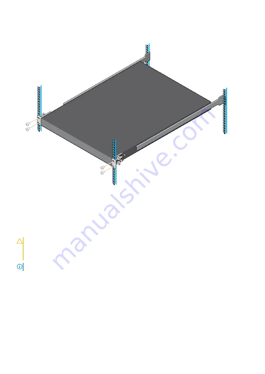
To remove the switch, remove the four screws from the L-brackets at the front of the rack and slide the switch forward.

To remove the rack rails from the rack, first remove the switch from the rack. Then remove the four outer rails screws at the
back of the rack.

DC power connections

Each DC PSU comes with one DC cable. The cable ships in a separate plastic bag.

CAUTION:

 This product must be supplied by a DC power source rated -48 Vdc to -60 Vdc, 40 A minimum, and

Tma = 45-degree C minimum. The altitude of operation is 5000 m. The product must be supplied by a UL-Listed
DC power source that is separated from AC mains by double or reinforced insulation when the switch is
connected to DC power. For more information, contact your Dell sales representative.

NOTE:

 You need a user-supplied Philips screwdriver to complete this installation.

Z9432F-ON switch installation

21

Summary of Contents for EMC PowerSwitch Z9432F-ON

Page 1: ...Dell EMC PowerSwitch Z9432F ON Setup Guide September 2020 September 2020 Rev A00 ...

Page 2: ...ential damage to hardware or loss of data and tells you how to avoid the problem WARNING A WARNING indicates a potential for property damage personal injury or death 2020 Dell Inc or its subsidiaries All rights reserved Dell EMC and other trademarks are trademarks of Dell Inc or its subsidiaries Other trademarks may be trademarks of their respective owners ...

Page 3: ...ts 7 Chapter 3 Z9432F ON switch installation 9 Unpack 9 Ground cable 9 Rack or cabinet installation 10 Z9432F ON installation 10 Four post ReadyRail installation 11 Four post L bracket rail installation 17 DC power connections 21 Optics installation 23 Optics removal 24 Switch power on 24 After switch installation 24 Chapter 4 Specifications 25 Chassis physical design 25 Chapter 5 Support 27 Conte...

Page 4: ...sible and invisible laser radiation may be emitted from the aperture of the optical transceiver ports Avoid exposure to laser radiation and do not stare into open apertures Regulatory Marketing model Z9432F ON is represented by the regulatory model E46W and the regulatory type E46W001 Topics Related documents Information Symbols Related documents For more information about the Z9432F ON switch see...

Page 5: ...n CAUTION The Caution icon signals information about situations that could result in equipment damage or loss of data NOTE The Warning icon signals information about hardware handling that could result in injury NOTE The ESD Warning icon requires that you take electrostatic precautions when handling the device About this guide 5 ...

Page 6: ...ontinuous temperature range is from 0 C to 45 C 32 F to 113 F The operating humidity is from 5 to 90 percent noncondensing continuous Install in a dry clean well ventilated and temperature controlled room away from heat sources such as hot cooling vents or direct sunlight Position away from sources of severe electromagnetic noise Position in a rack or cabinet or on a desktop with adequate space in...

Page 7: ...n internal temperature monitoring The switch never intentionally turns off the fans Power Connect the switch to the applicable power source using the appropriate power cable An AC power cable is included with the switch When installing AC or DC switches follow the code requirements appropriate for your country region For example in the U S follow National Electrical Code ANSI NFPA 70 and in Europe...

Page 8: ...e mishandled Always wear an ESD preventive wrist or heel ground strap when handling the switch and its accessories After you remove the original packaging place the Z9432F ON switch and its components on an anti static surface 8 Site preparations ...

Page 9: ...9432F ON switch One RJ45 to DB 9 female cable Two sets of rail kits no tools required Two PSUs Seven fan units Two country and region specific AC power cables Dell EMC PowerSwitch Z9432F ON Set up Guide Safety and Regulatory Information Warranty and Support Information 1 Place the container on a clean flat surface and cut all straps securing the container 2 Open the container or remove the contain...

Page 10: ...tside rail WARNING This guide is a condensed reference Read the safety instructions in your Safety Environmental and Regulatory information booklet before you begin NOTE The figures are not intended to represent a specific switch NOTE Do not the use the mounted rails as a shelf or a workplace Rack mount safety considerations Rack loading Overloading or uneven loading of racks may result in shelf o...

Page 11: ...post rack 3 Slide the switch into the rack NOTE You need a user supplied Phillips screwdriver to complete this installation To install the switch 1 Remove the rails rail plates and screws from the shipping container 2 Separate the inner rail and the outer rail Press the rail clip and pull the inner rail out 3 Attach the inner rail to the switch Line up the inner rail slot with the T stud on the sw...

Page 12: ...A 9 5 mm 354 in square hole EIA 7 1 mm 279 in round hole or M5 threaded For EIA 9 5 mm 354 in square hole racks default setting for the outer rail For EIA 7 1 mm 279 in round hold racks press the latch to change from square pegs to round pegs 12 Z9432F ON switch installation ...

Page 13: ...parts on both the front and rear side of the outer rail 5 Attach the outer rail to the back of the four post rack Align the outer rail pegs to the back of the four post rack and push towards the back to lock the outer rail to the rear post The rail clicks into place M5 threaded mounting rack OR 9 5 mm square hole rack Z9432F ON switch installation 13 ...

Page 14: ...he outer rail to the front of the four post rack The rail clicks into place 7 Repeat these steps for the second rail 8 Slide the inner rails attached to the switch into the outer rails that are attached to the rails 14 Z9432F ON switch installation ...

Page 15: ...NOTE Press the spring clip on each outer rail to allow the switch to slide into the outer rail 9 Tighten the thumbscrews to secure the switch to the rack Z9432F ON switch installation 15 ...

Page 16: ...tch press the rail spring clip and pull the inner rail and switch out of the outer rail and rack To remove the outer rails from the rack press the blue plastic button on each outer rail 16 Z9432F ON switch installation ...

Page 17: ...t rack 4 Slide the switch into the rack 5 Secure the L brackets to the front of the four post rack NOTE You need a user supplied Phillips screwdriver to complete this installation NOTE For the EIA 9 5 mm 354 in square hole rack insert the cage nuts into the rack holes before you secure the L brackets to the rack The cage nuts ship with the brackets and rails To install the switch 1 Remove the rail...

Page 18: ...ter rail 4 Attach the inner rail to the switch Line up the slot on the inner rail with the T stud on the switch Push back to lock the rail into place Secure the inner rail to the switch using two M4 screws 18 Z9432F ON switch installation ...

Page 19: ... of the four post rack Align the outer rail peg to the back of the four post rack Secure the outer rail to the back of the rack using two M4 screws for each rail Repeat this step to attach the second outer rail to the other side of the rack 6 Slide the inner rails into the outer rails Z9432F ON switch installation 19 ...

Page 20: ...s to the front of the four post rack Align the L bracket holes to the holes at the front of the four post rack Secure the L brackets to the front of the rack using two M4 screws for each side 20 Z9432F ON switch installation ...

Page 21: ...ips in a separate plastic bag CAUTION This product must be supplied by a DC power source rated 48 Vdc to 60 Vdc 40 A minimum and Tma 45 degree C minimum The altitude of operation is 5000 m The product must be supplied by a UL Listed DC power source that is separated from AC mains by double or reinforced insulation when the switch is connected to DC power For more information contact your Dell sale...

Page 22: ...green wire is the ground wire 10 AWG minimum 3 Use a user supplied flat head screwdriver to tighten the screws that secures the bare wires into the wiring block 4 Remove the plastic cover the two M4 screws and one M5 screw from the PSU socket Keep all the removed parts 5 Attach the blue wire and black wire to the PSU socket Secure the wires with the two M4 screws NOTE Attach the blue wire to the V...

Page 23: ...tical fibers follow all warning labels and always wear eye protection Never look directly into the end of a terminated or unterminated fiber or connector as it may cause eye damage 1 Position the optic so it is in the correct position The optic has a key that prevents it from being inserted incorrectly 2 Insert the optic into the port until it gently snaps into place NOTE When you cable the ports ...

Page 24: ...ficient overcurrent protection devices All protective covers are in place If you do not install optional modules blank panels are installed CAUTION Do not turn on the switch if you did not install a fan module NOTE A US AC power cable is included for powering up an AC power supply You must order all other power cables separately NOTE If components are mishandled ESD damage can occur Always wear an...

Page 25: ...nts 11 78 kg 2 PSUs and 7 fans 25 97 lbs 2 PSUs and 7 fans Rack clearance required Front 12 7 cm 5 inches Back 12 7 cm 5 inches Table 2 Environmental parameters Parameter Specifications Operating temperature 0 C 45 C 32 F 113 F continuously NOTE Reduce maximum temperature by 1 C 125 meters 1 F 228 ft above 950 meters 3 117 ft Operating humidity 5 90 RH noncondensing Storage temperature 40 C 70 C 4...

Page 26: ...ing 100 duty cycle 9 1 bels Table 3 AC power requirements Parameter Specifications Power supply 90 130 VAC 110 VAC nominal 180 264 VAC 240 VAC nominal Maximum current draw per system 12 0 10 0 A at 100 120 VAC one PSU operating 6 8 5 7 A at 200 240 VAC two PSUs operating Maximum power consumption 28x15W and 4x20W QSFP56 DD optics Low Line VAC 1200 W one PSU operating Low Line VAC 1362 W two PSUs o...

Page 27: ...r country from the drop down menu To obtain product specific information enter the 7 character service tag which is known as a luggage tag or 11 digit express service code of your switch and click Submit To view the chassis service tag or express service code pull out the tag or enter the show chassis command from the CLI To receive more technical support click Contact Us On the Contact Informatio...

Reviews: