


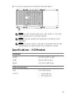


Feature
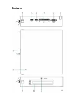
1.
Cable routing slot
Route any cable(s) that has to be
connected to the PCI card installed in
the I/O module.
2.
RS232 port
Connect a RS2325 cable.
3.
GPIO port
Connect a GPIO 8–pin cable.
4.
USB 2.0 port
For USB 2,0 devices
5.
USB 2.0 port
For USB 2,0 devices
6.
Top release-latch
Push both the top and bottom release-
latch to disconnect the power module
from the Dell Edge Gateway.
7.
I/O module expansion
connector and guide pin
Connect the I/O module to the Dell
Edge Gateway.
8.
Power status light
Indicates the power state of the I/O
module and the Dell Edge Gateway.
9.
Bottom release-latch
Push both the top and bottom release-
latch to disconnect the power module
from the Dell Edge Gateway.
10. PCIe x1 card slot
Install PCIe x1 card on the I/O module.
11. I/O module cover removal
screw
Remove the screw to open the box and
install the PCIe card.
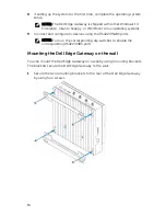
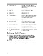
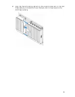
Setting up the I/O Module
CAUTION: Before touching anything inside the system, ground
yourself by touching an unpainted metal surface. While you work,
periodically touch an unpainted metal surface to dissipate static
electricity, which could harm internal components.
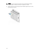
NOTE: Install the PCIe expansion card in the I/O Expansion Module
before mounting it on Wall mount or DIN rail.
1
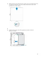
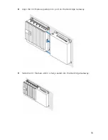
Install the PCIe expansion card in the I/O Expansion Module - optional
30
Summary of Contents for Edge Gateway 5000 Series
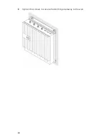
Page 18: ...3 Tighten the screws to secure the Dell Edge Gateway to the wall 18 ...
Page 22: ...5 Close the micro SIM card tray 6 Power on your Gateway 22 ...
Page 29: ...Features 29 ...
Page 50: ...Environmental requirements Storage 15 20 m to 10 668 m 50 ft to 35 000 ft 50 ...
Page 57: ...7 Connect the intrusion switch to the Gateway 57 ...