Table 5. Right control panel
Item
Indicator or button
Icon
Description
5
VGA port
Enables you to connect a display device to the system. For more information,
see the Dell EMC PowerEdge R7515 Technical Specifications.
NOTE:
For the system to power on successfully, ensure the right control panel is connected well to the system.
NOTE:
For more information about the ports, see the Dell EMC PowerEdge R7515 Technical Specifications.
Rear view of the system
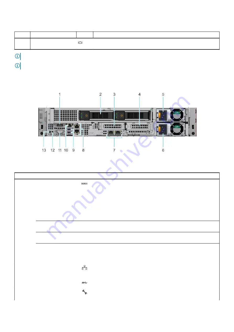
Figure 7. Rear view of the system with two rear drives
Table 6. Rear view of the system with two rear drives
Item
Ports, panels, or slots
Icon
Description
1
Serial port
Enables you to connect a serial device to the system.
2
Drive
N/A
Enables you to install drives that are supported on your system.
3
PCIe expansion card riser
1A (slot 2)
N/A
The expansion card riser enables you to connect PCI Express
expansion cards.
4
PCIe expansion card riser
2 (slot 3)
N/A
The expansion card riser enables you to connect PCI Express
expansion cards.
5
Power supply unit (PSU)
N/A
For information about the PSU configurations, see the Dell EMC
PowerEdge R7515 Technical Specifications.
6
Power supply unit (PSU)
N/A
For information about the PSU configurations, see the Dell EMC
PowerEdge R7515 Technical Specifications.
7
LOM Riser Ethernet port
(2) (Optional) (slot 1)
The NIC ports that are integrated on the LAN on Motherboard
(LOM) riser provide network connectivity. For more information
about the supported configurations, see theDell EMC PowerEdge
R7515 Technical Specifications.
8
Ethernet ports (2)
The Ethernet ports that are integrated on the system board
provide network connectivity. These NIC ports can also be shared
with iDRAC when iDRAC network settings is set to shared mode.
9
USB 3.0 port (2)
These USB ports support USB 3.0.
10
iDRAC dedicated port
Enables you to remotely access iDRAC. For more information, see
the iDRAC User’s Guide at
System overview
13


