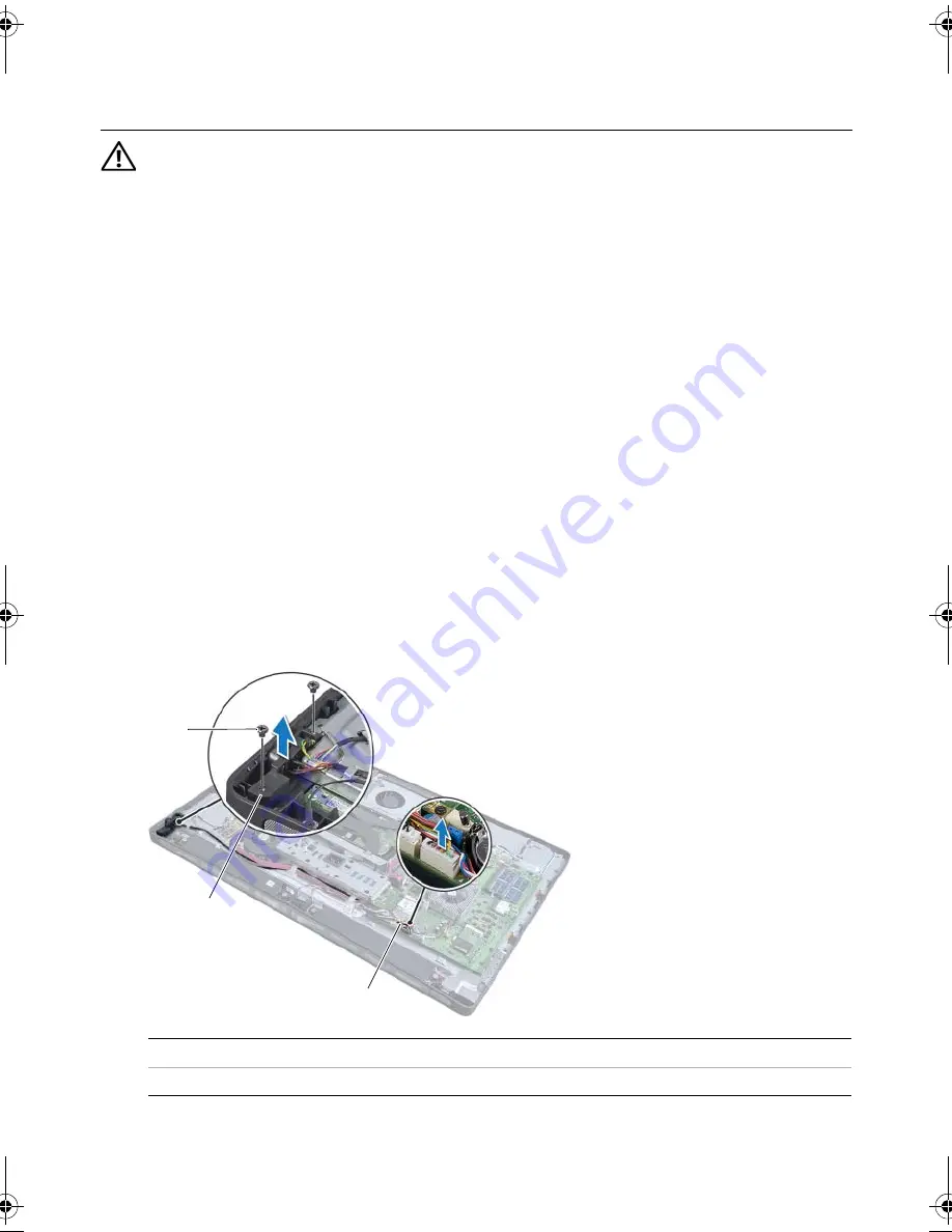
Removing the Power-Button Assembly |
119
54
Removing the Power-Button Assembly
WARNING: Before working inside your computer, read the safety information
that shipped with your computer and follow the steps in "Before You Begin" on
page 11. After working inside your computer, follow the instructions in "After
Working Inside Your Computer" on page 13. For additional safety best practices
information, see the Regulatory Compliance Homepage at dell.com/
regulatory_compliance.
Prerequisites
1
Remove the back cover. See "Removing the Back Cover" on page 19.
2
Remove the system-board shield. See "Removing the System-Board Shield" on
page 31.
3
Remove the trim cover. See "Removing the Trim Cover" on page 87.
4
Remove the inner frame. See "Removing the Inner Frame" on page 95
Procedure
1
Disconnect the power-button cable from the system board.
2
Remove the power-button cable from its routing guides.
3
Remove the screws that secure the power-button assembly to the computer base.
4
Press the power button inward to release it from the slot on the computer base and
then gently lift the power-button assembly off the computer base.
1
screws (2)
2
power-button assembly
3
power-button cable
2
3
1
OM_Book.book Page 119 Friday, April 27, 2012 3:23 PM
Summary of Contents for dxcwrk1 - XPS - One
Page 14: ...14 After Working Inside Your Computer ...
Page 18: ...18 Technical Overview ...
Page 20: ...20 Removing the Back Cover ...
Page 22: ...22 Replacing the Back Cover ...
Page 24: ...24 Removing the Converter Board ...
Page 26: ...26 Replacing the Converter Board ...
Page 30: ...30 Replacing the Optical Drive ...
Page 32: ...32 Removing the System Board Shield ...
Page 34: ...34 Replacing the System Board Shield ...
Page 38: ...38 Replacing the Power Supply Unit ...
Page 42: ...42 Replacing the Memory Module s ...
Page 44: ...44 Removing the Coin Cell Battery ...
Page 46: ...46 Replacing the Coin Cell Battery ...
Page 48: ...48 Removing the Stand ...
Page 50: ...50 Replacing the Stand ...
Page 54: ...54 Replacing the Hard Drive ...
Page 56: ...56 Removing the Hard Drive Cage ...
Page 58: ...58 Replacing the Hard Drive Cage ...
Page 60: ...60 Removing the Power Supply Fan ...
Page 62: ...62 Replacing the Power Supply Fan ...
Page 64: ...64 Removing the TV Tuner Mini Card ...
Page 66: ...66 Replacing the TV Tuner Mini Card ...
Page 70: ...70 Replacing the Wireless Mini Card ...
Page 72: ...72 Removing the mSATA Mini Card ...
Page 74: ...74 Replacing the mSATA Mini Card ...
Page 76: ...76 Removing the Processor Heat Sink Fan ...
Page 78: ...78 Replacing the Processor Heat Sink Fan ...
Page 80: ...80 Removing the Processor Heat Sink ...
Page 82: ...82 Replacing the Processor Heat Sink ...
Page 84: ...84 Removing the Processor ...
Page 88: ...88 Removing the Trim Cover ...
Page 90: ...90 Replacing the Trim Cover ...
Page 92: ...92 Removing the I O Panel ...
Page 94: ...94 Replacing the I O Panel ...
Page 96: ...96 Removing the Inner Frame ...
Page 98: ...98 Replacing the Inner Frame ...
Page 102: ...102 Replacing the I O Board ...
Page 104: ...104 Removing the TV In Port ...
Page 106: ...106 Replacing the TV In Port ...
Page 110: ...110 Replacing the Infrared Emitter Port ...
Page 116: ...116 Removing the Speakers ...
Page 118: ...118 Replacing the Speakers ...
Page 120: ...120 Removing the Power Button Assembly ...
Page 122: ...122 Replacing the Power Button Assembly ...
Page 126: ...126 Replacing the Side I O Board ...
Page 130: ...130 Removing the Middle Cover ...
Page 144: ...144 Replacing the Camera Module ...
Page 148: ...148 Replacing the Microphone Modules ...
Page 152: ...152 Replacing the Infrared IR Module ...
Page 156: ...156 Replacing the Antenna Module s ...
Page 166: ...166 Flashing the BIOS ...


