background image

Adding Parts

63

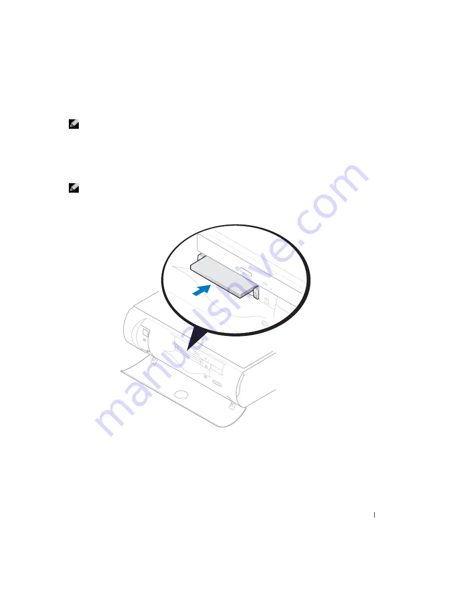
Installing a PC Card


NOTE: 

The length of some PC Cards may prevent the front-panel door from closing.

PC Cards are generally marked with a symbol (such as a triangle or an arrow) to indicate which end 
to insert into the slot, and the cards are keyed to prevent incorrect insertion. If card orientation is 
not clear, see the documentation supplied with the card.

1

Hold the card with its orientation symbol pointing into the slot and the top side of the card 
facing up. 


NOTE: 

A PC Card is not a bootable device.

2

Insert the card into the slot, and press firmly until the card is completely seated in the internal 
PC Card connector. 

3

If you encounter too much resistance when you insert the card, do not force the card. Check 
the card's orientation, and try again.

4

Your computer recognizes most PC Cards and automatically loads the appropriate device 
driver for use with the computer. If the configuration program tells you to load the 
manufacturer's drivers, install them with the CD that accompanied the PC Card.

Summary of Contents for Dimension 4600C

Page 1: ...ated IEEE 1394 connectors On computers with integrated PC Card connectors optional video card connector see the setup diagram parallel connector USB 2 0 connectors 6 microphone connector voltage selection switch mouse connector diagnostic lights 4 integrated video connector power connector keyboard connector line in connector center LFE connector SPDIF out connector modem connectors 2 IEEE 1394 co...

Page 2: ... 2003 2004 Dell Inc All rights reserved Reproduction in any manner whatsoever without the written permission of Dell Inc is strictly forbidden Trademarks used in this text Dell the DELL logo Inspiron Dell Precision Dimension OptiPlex DellNet PowerApp PowerVault PowerEdge PowerConnect Axim and Latitude are trademarks of Dell Inc Intel Pentium and Celeron are registered trademarks of Intel Corporati...

Page 3: ...Connecting a USB Printer 15 Connecting an IEEE 1394 Device Optional 16 Setting Up a Home and Office Network 16 Connecting to a Network Adapter 16 Network Setup Wizard 17 Connecting to the Internet 18 Setting Up Your Internet Connection 18 Copying CDs and DVDs 19 How to Copy a CD or DVD 19 Using Blank CD Rs and CD RWs 20 Helpful Tips 20 Hyper Threading 20 Booting to a USB Device 21 Turning Off Your...

Page 4: ...ponding 30 A program crashes repeatedly 30 A program is designed for an earlier Microsoft Windows operating system 30 A solid blue screen appears 31 Other software problems 31 Other technical problems 32 General hardware problems 32 IEEE 1394 Device Problems 33 Keyboard Problems 33 Mouse Problems 34 Network Problems 35 PC Card Problems 35 Power Problems 36 Printer Problems 37 Scanner Problems 38 S...

Page 5: ...ers 49 Restoring Your Operating System 49 Using Microsoft Windows XP System Restore 50 Using Dell PC Restore by Symantec 51 Resolving Software and Hardware Incompatibilities 52 4 Adding Parts Front and Back View of the Computer 53 Front View 53 Back View 55 Reattaching the Front Door 57 Opening the Computer Cover 58 Looking Inside Your Computer 60 System Board 61 Adding PC Cards Optional 62 PC Car...

Page 6: ... Appendix Specifications 73 Standard Settings 77 Viewing Settings 78 System Setup Screens 78 Clearing Forgotten Passwords 78 Replacing the Battery 79 Dell Technical Support Policy U S Only 81 Definition of Dell Installed Software and Peripherals 81 Definition of Third Party Software and Peripherals 81 FCC Notices U S Only 82 Class A 82 Class B 82 FCC Identification Information 83 Contacting Dell 8...

Page 7: ...Safety Instructions 7 Safety Instructions See your Product Information Guide for safety instructions ...

Page 8: ...8 Safety Instructions w w w d e l l c o m s u p p o r t d e l l c o m ...

Page 9: ...g Windows How to clean my computer How to use my mouse and keyboard Tell Me How Help File 1 Click the Start button and click Help and Support 2 Click User and system guides and click User s guides 3 Click Tell Me How Express Service Code and Service Tag Microsoft Windows License Label Express Service Code and Product Key Label These labels are located on your computer ...

Page 10: ...r Dell customers Upgrades Upgrade information for components such as memory the hard drive and the operating system Customer Care Contact information order status warranty and repair information Downloads Drivers patches and software updates Reference Computer documentation product specifications and white papers How to use Windows XP Documentation for my computer Documentation for devices such as...

Page 11: ... outlet do not permit contact between the green ground wire and power leads because electrical shock fire or damage to your computer can occur see the following figure If you decide not to connect the green ground wire to an electrical outlet go to step 3 2 Connect the metal ground connector to the grounding source on the outlet see the following figure a Loosen the grounding source b Slide the me...

Page 12: ...the safety instructions in the Product Information Guide NOTE Place your computer on a soft surface to prevent scratching the top cover To attach the stand 1 Rotate the computer to an upside down position 2 Insert the screw into the bottom of the stand 3 Align the two tabs and the screw on the stand with the tab holes and screw hole in the bottom of the computer tabs 2 tab holes 2 screw screw hole...

Page 13: ...omputer in a horizontal position until you reattach the stand Setting Up a Printer NOTICE Complete the operating system setup before you connect a printer to the computer See the documentation that came with the printer for setup information including how to Obtain and install updated drivers Connect the printer to the computer Load paper and install the toner or ink cartridge Contact the printer ...

Page 14: ...w the safety instructions in the Product Information Guide 1 Complete the operating system setup if you have not already done so 2 Turn off the computer see page 21 NOTICE For best results use a 3 m 10 ft or shorter parallel cable 3 Attach the parallel printer cable to the parallel connector on the computer and tighten the two screws Attach the cable to the connector on the printer and snap the tw...

Page 15: ...the operating system setup if you have not already done so 2 Install the printer driver if necessary See the documentation that came with your printer 3 Attach the USB printer cable to the USB connectors on the computer and the printer The USB connectors fit only one way USB printer cable USB connector on computer USB connector on printer ...

Page 16: ...x pin IEEE 1394 devices with the use of an adapter Setting Up a Home and Office Network Connecting to a Network Adapter Before you connect your computer to a network the computer must have a network adapter installed and a network cable connected to it To connect a network cable 1 Connect the network cable to the network adapter connector on the back of your computer NOTE Insert the cable until it...

Page 17: ...o All Programs Accessories Communications and then click Network Setup Wizard 2 On the welcome screen click Next 3 Click Checklist for creating a network NOTE Selecting the This computer connects directly to the Internet connection method enables the integrated firewall provided with Windows XP 4 Complete the checklist and required preparations 5 Return to the Network Setup Wizard and follow the i...

Page 18: ...cable modem connection contact your ISP for setup instructions Setting Up Your Internet Connection To set up an AOL or MSN connection 1 Save and close any open files and exit any open programs 2 Double click the MSN Explorer or AOL icon on the Windows desktop 3 Follow the instructions on the screen to complete the setup If you do not have an MSN Explorer or AOL icon on your desktop or if you want ...

Page 19: ...onic RecordNow click the question mark icon in the upper right corner of the window and click RecordNow Help or RecordNow Tutorial How to Copy a CD or DVD NOTE If you have a DVD CD RW combo drive and you experience recording problems check for available software patches at the Sonic support website at support sonic com NOTE Most commercial DVDs have copyright protection and cannot be copied using ...

Page 20: ...apacity for example do not copy a 650 MB file to a 650 MB blank CD The CD RW drive needs 1 or 2 MB of the blank CD to finalize the recording Use a blank CD RW to practice CD recording until you are familiar with CD recording techniques If you make a mistake you can erase the data on the CD RW and try again You can also use blank CD RWs to test music file projects before you record the project perm...

Page 21: ...ss F12 immediately If you wait too long and the Microsoft Windows logo appears continue to wait until you see the Windows desktop Then shut down your computer through the Start menu and try again NOTE This changes the boot sequence for one time only On the next start up the computer boots according to the devices specified in the system setup program 4 When the boot device list appears highlight U...

Page 22: ...22 Setting Up and Using Your Computer w w w d e l l c o m s u p p o r t d e l l c o m ...

Page 23: ...out where to go for answers Use this chart to help you quickly find the answers to your questions See page 36 See page 29 Get technical assistance from Dell See page 83 Press a key or move the mouse See the Tell Me How help file for information on standby mode For more information see page 25 ...

Page 24: ...ms w w w d e l l c o m s u p p o r t d e l l c o m See page 40 See page 39 See page 37 See page 27 See page 34 See page 33 See page 26 See page 35 See page 30 See page 38 See page 29 See page 27 See page 27 See page 30 ...

Page 25: ...rt button and click Help and Support 2 Click User and system guides and click User s guides 3 Click Tell Me How TO ACCESS WINDOWS HELP 1 Click the Start button and click Help and Support 2 Type a word or phrase that describes your problem and click the arrow icon 3 Click the topic that describes your problem 4 Follow the instructions shown on the screen TO LOCATE ADDITIONAL INFORMATION FOR YOUR CO...

Page 26: ...Speaker Problems on page 39 ENSURE THAT WINDOWS RECOGNIZES THE DRIVE Click the Start button and click My Computer If the CD drive is not listed perform a full scan with your antivirus software to check for and remove viruses Viruses can sometimes prevent the Microsoft Windows operating system from recognizing the drive CLEAN THE DISC See the Tell Me How help file for instructions on cleaning your ...

Page 27: ...Viruses can sometimes prevent Windows from recognizing the drive CLEAN THE DISC See the Tell Me How help file for instructions on cleaning your DVDs To access help files see page 25 CHECK FOR INTERRUPT REQUEST CONFLICTS See page 52 RUN CHECK DISK 1 Click the Start button and click My Computer 2 Right click the drive letter local disk that you want to scan for errors and then click Properties 3 Cli...

Page 28: ...lick Phone and Modem Options 4 Click the Modems tab 5 Click the COM port for your modem 6 Click Properties click the Diagnostics tab and then click Query Modem to verify that the modem is communicating with Windows If all commands receive responses the modem is operating properly TURN OFF CALL WAITING CATCH PHONE See your telephone directory for instructions on deactivating this feature Then adjus...

Page 29: ...move Programs 3 Select the program you want to remove 4 Click the Change or Remove Program icon 5 See the program documentation for installation instructions INSERT BOOTABLE MEDIA The operating system is trying to boot to a nonbootable CD Insert a bootable CD NOT ENOUGH MEMORY OR RESOURCES CLOSE SOME PROGRAMS AND TRY AGAIN You have too many programs open Close all windows and open the program that...

Page 30: ...lose data if you are unable to perform an operating system shutdown END THE PROGRAM 1 Press Ctrl Shift Esc simultaneously 2 Click Applications 3 Click the program that is no longer responding 4 Click End Task CHECK THE SOFTWARE DOCUMENTATION Many software manufacturers maintain websites with information that may help you solve the problem Ensure that you properly installed and configured the progr...

Page 31: ... AN ERROR WHILE ENTERING DATA See the program documentation to ensure that the values or characters you are entering are valid CHECK FOR VIRUSES Use a virus scanning program to check the hard drive or CDs RESTART THE COMPUTER Save and close any open files exit any open programs and then shut down your computer through the Start menu instead of by pressing the power button Otherwise you may lose da...

Page 32: ...uch as Dell Forum a chat room where you can communicate with other Dell customers about their computers and gain access to technical support through e mail See Dell Support Website on page 9 for more information about the website See Dell Technical Support Policy U S Only on page 81 for a description of the hardware and software support provided by Dell CALL DELL If you cannot solve your problem u...

Page 33: ... Start menu see page 21 After the computer shuts down press the power button to restart the computer If the computer does not respond to a keystroke or the mouse press the power button for at least 8 to 10 seconds until the computer turns off Press the power button again to restart the computer CHECK THE KEYBOARD CABLE Ensure that the keyboard cable is firmly connected to the computer Shut down th...

Page 34: ...MPUTER REMOVE THE POWER CABLE AND THEN RECONNECT THE MOUSE CABLE If the mouse is connected after the power is turned on the mouse appears to be nonfunctional To make the mouse function properly 1 While your computer is on remove the power cable from the back of the computer 2 Connect the mouse to the computer 3 Reconnect the power cable 4 Turn on your computer Pressing the power button does not cl...

Page 35: ...k communication exists Replace the network cable RESTART THE COMPUTER AND TRY TO LOG ON TO THE NETWORK AGAIN CHECK YOUR NETWORK SETTINGS Contact your network administrator or the person who set up your network to verify that your network settings are correct and that the network is functioning CHECK FOR INTERRUPT REQUEST CONFLICTS See page 52 CHECK THE PC CARD Ensure that the PC Card is properly i...

Page 36: ... The computer is either turned off or is not receiving power Reseat the power cable into both the power connector on the back of the computer and the electrical outlet If the computer is plugged into a power strip ensure that the power strip is plugged into an electrical outlet and that the power strip is turned on Ensure that the electrical outlet is working by testing it with another device such...

Page 37: ...e same circuit or operating near the computer can cause interference Other causes of interference are Power extension cables Keyboard and mouse extension cables Too many devices on a power strip Multiple power strips connected to the same electrical outlet CHECK THE PRINTER DOCUMENTATION See the printer documentation for setup and troubleshooting information ENSURE THAT THE PRINTER IS TURNED ON Se...

Page 38: ...owing port s setting is USB REINSTALL THE PRINTER DRIVER See the printer documentation for instructions CHECK THE SCANNER DOCUMENTATION See the scanner documentation for setup and troubleshooting information UNLOCK THE SCANNER Ensure that your scanner is unlocked if it has a locking tab or button RESTART THE COMPUTER AND TRY THE SCANNER AGAIN CHECK THE CABLE CONNECTIONS If your scanner has a power...

Page 39: ...e volume is turned up and that the sound is not muted DISCONNECT HEADPHONES FROM THE HEADPHONE CONNECTOR Sound from the speakers is automatically disabled when headphones are connected to the computer s front panel headphone connector TEST THE ELECTRICAL OUTLET Ensure that the electrical outlet is working by testing it with another device such as a lamp ENABLE DIGITAL MODE Your speakers do not wor...

Page 40: ...click the name of your CD drive 5 Click the Properties tab 6 Uncheck the Enable digital CD audio for this CD ROM device box ADJUST THE WINDOWS VOLUME CONTROL Click or double click the speaker icon in the lower right corner of your screen Ensure that the volume is turned up and that the sound is not muted CHECK THE MONITOR POWER LIGHT If the power light is off firmly press the button to ensure that...

Page 41: ...OM THE MONITOR If your speaker system includes a subwoofer ensure that the subwoofer is at least 60 cm 2 ft away from the monitor MOVE THE MONITOR AWAY FROM EXTERNAL POWER SOURCES Fans fluorescent lights halogen lamps and other electrical devices can cause the screen image to appear shaky Turn off nearby devices to check for interference ROTATE THE MONITOR TO FACE A DIFFERENT DIRECTION Eliminate s...

Page 42: ...42 Solving Problems w w w d e l l c o m s u p p o r t d e l l c o m ...

Page 43: ...he lights remain green If the computer malfunctions the color and sequence of the lights identify the problem CAUTION Before you begin any of the procedures in this section follow the safety instructions in the Product Information Guide Light Pattern Problem Description Suggested Resolution The computer is in a normal off condition or a possible pre BIOS failure has occurred Verify that the comput...

Page 44: ...working memory of the same type into your computer see page 68 If the problem persists contact Dell see page 83 A possible expansion card failure has occurred 1 Determine if a conflict exists by removing a card not the video card see page 65 and then restarting the computer 2 If the problem persists reinstall the card that you removed remove a different card and then restart the computer 3 Repeat ...

Page 45: ... has occurred Reinstall all USB devices check cable connections and then restart the computer No memory modules are detected Reinstall all memory modules see page 68 and restart the computer To eliminate the possibility of a faulty memory connector remove all memory modules see page 68 reinstall one memory module if the computer supports a single module and then restart the computer If the compute...

Page 46: ...any times a test is run Display test results Suspend testing if an error is detected Access online help information that describes the tests and devices Memory modules are detected but a memory configuration or compatibility error exists Ensure that there are no special memory module memory connector placement requirements see page 68 Verify that the memory modules that you are installing are comp...

Page 47: ...he Main Menu screen appears click the button for the option you want NOTE The Service Tag number for your computer is located at the top of each test screen 2 If a problem is encountered during a test a message displaying the error code and a description of the problem appear Write down the error code and problem description and follow the instructions on the screen If you cannot resolve the error...

Page 48: ...erform the steps in the following sections to identify whether the driver is the source of your problem and if necessary to update the driver Identifying Drivers 1 Click the Start button and click Control Panel 2 In the Control Panel window under Pick a Category click Performance and Maintenance 3 In the Performance and Maintenance window click System 4 In the System Properties window click the Ha...

Page 49: ...ndow under Pick a Category click Performance and Maintenance 3 In the Performance and Maintenance window click System 4 In the System Properties window click the Hardware tab 5 Click Device Manager 6 In the Device Manager window right click the device for which the new driver was installed and click Properties 7 Click the Drivers tab 8 Click Roll Back Driver If Device Driver Rollback does not reso...

Page 50: ...back see page 50 to resolve the problem If that is unsuccessful then use System Restore NOTICE Before you restore the computer to an earlier operating state save and close any open files and exit any open programs Do not alter open or delete any files or programs until the system restoration is complete 1 Click the Start button point to All Programs Accessories System Tools and then click System R...

Page 51: ...ve and removes any applications or drivers installed after you received your computer If possible back up the data before using PC Restore To use PC Restore 1 Turn on the computer During the boot process a blue bar with www dell com appears at the top of the screen 2 Immediately upon seeing the blue bar press Ctrl F11 If you do not press Ctrl F11 in time let the computer finish restarting and then...

Page 52: ...ick Performance and Maintenance and click System 3 Click the Hardware tab and click Device Manager 4 In the Device Manager list check for conflicts with the other devices Conflicts are indicated by a yellow exclamation point beside the conflicting device or a red X if the device has been disabled 5 Double click any conflict to display the Properties window If an IRQ conflict exists the Device stat...

Page 53: ...g Parts 53 Adding Parts Front and Back View of the Computer Front View NOTE The front panel door does not close when you are using certain PC Cards or IEEE 1394 USB or headphone connectors 9 8 7 3 5 6 1 2 4 ...

Page 54: ...rs and keyboards NOTICE This computer supports the use of a USB hub However do not connect two or more USB hubs to a USB connector Doing so may cause the computer to unexpectedly restart NOTE If you attach a USB device that was not included in your original computer order you may need to install a specific driver to make the device work Check the documentation that came with the device or contact ...

Page 55: ...iew NOTE The front panel door is removable if you remove it or accidentally knock it off its hinges it snaps back in place For instructions on how to reattach the door see page 57 4 1 12 11 7 2 16 17 6 13 3 18 5 8 9 10 14 15 ...

Page 56: ...rk cable to either a network jack or your network device Connect the other end of the network cable to the network adapter connector on the back panel of your computer A click indicates that the network cable has been securely attached On computers with a network connector card use the connector on the card It is recommended that you use Category 5 wiring and connectors for your network If you mus...

Page 57: ...such as printers and keyboards It is recommended that you use the front USB connectors for devices that you connect occasionally such as joysticks or cameras 13 microphone connector Use the pink microphone connector to attach a personal computer microphone for voice or musical input into a sound or telephony program 14 center LFE connector Use the yellow center LFE connector available on computers...

Page 58: ...e Start menu see page 21 2 Ensure that your computer and attached devices are turned off If your computer and attached devices did not automatically turn off when you shut down your computer turn them off now NOTICE To disconnect a network cable first unplug the cable from your computer and then unplug it from the network wall jack 3 Disconnect any telephone or telecommunication lines from the com...

Page 59: ...st 30 cm 1 ft of desk top space 6 Locate the two release buttons shown in the illustration Then press the two release buttons as you lift the cover NOTICE Open the cover slowly to ensure that you do not damage any cables 7 Raise the back of the cover and pivot it toward the front of the computer NOTE Make sure that the computer is oriented with the cable security tab on top as shown in the illustr...

Page 60: ... located in the Product Information Guide CAUTION To guard against electrical shock always unplug your computer from the electrical outlet before opening the cover NOTICE Be careful when opening the computer cover to ensure that you do not inadvertently disconnect cables from the system board hard drive card slots power supply heat sink and blower assembly system board CD or DVD drive ...

Page 61: ...sor connector CPU microprocessor fan connector FAN front panel switch connector FRONTPANEL CD audio connector CD IN front panel audio cable connector FRONTAUDIO telephony voice modem connector MODEM video card connector AGP back of computer microprocessor power connector 12VPOWER PCI1 card connector PCI2 page 65 standby power light AUX_PWR password jumper PWD1 page 78 serial ATA connector SATA1 ...

Page 62: ...hat support the following four combinations of cards NOTE Your computer is designed for either 5 V or 3 3 V 16 bit PCMCIA cards Some cards are keyed for 3 3 V only but will not fit into the PC slot Cards are keyed to prevent incorrect insertion into the slot If card orientation is not clear see the documentation supplied with the card A single Type I or Type II card using either the upper or lower...

Page 63: ...n symbol pointing into the slot and the top side of the card facing up NOTE A PC Card is not a bootable device 2 Insert the card into the slot and press firmly until the card is completely seated in the internal PC Card connector 3 If you encounter too much resistance when you insert the card do not force the card Check the card s orientation and try again 4 Your computer recognizes most PC Cards ...

Page 64: ...before you remove it from the computer If you do not remove the card in the configuration utility you could lose data from open programs NOTE Press the button with the upper dot to eject the top card and the button with the lower dot to eject the bottom card NOTICE Do not attempt to eject a card by pulling its dongle if one is attached Press the eject button and gently remove the card ...

Page 65: ...al shock always unplug your computer from the electrical outlet before opening the cover 6 Open the computer cover see page 58 7 Press the lever on the retention arm and raise the retention arm 8 If you are installing a new card remove the filler bracket to create an empty card slot opening If you are replacing a card that is already installed in the computer remove the card If necessary disconnec...

Page 66: ...the procedures in this section follow the safety instructions located in the Product Information Guide NOTE You must use low profile cards for your computer A full size card can cause damage to the computer or the card Your Dell computer provides a connector for an AGP card 1 Shut down the computer through the Start menu see page 21 2 Ensure that your computer and attached devices are turned off I...

Page 67: ...bracket by raising the hinged lever and sliding the filler bracket up 2 Press the card lever toward the PCI connector 3 Pull the card up and out of the card clip filler bracket hinged lever back of computer tab card clip lever notch PCI connector AGP connector ...

Page 68: ...connector NOTICE To connect a network cable first plug the cable into the network wall jack and then plug it into the computer 7 Connect your computer and devices to electrical outlets and turn them on Adding Memory You can increase your computer memory by installing memory modules on the system board For information on the type of memory supported by your computer see Memory on page 74 NOTE DDR 3...

Page 69: ... covered under your computer warranty Installing Memory CAUTION Before you begin any of the procedures in this section follow the safety instructions located in the Product Information Guide 1 Shut down the computer through the Start menu see page 21 2 Ensure that your computer and attached devices are turned off If your computer and attached devices did not automatically turn off when you shut do...

Page 70: ...To avoid damage to the memory module press the module straight down into the connector while you apply equal force to each end of the module 9 Insert the module into the connector until the module snaps into position If you insert the module correctly the securing clips snap into the cutouts at each end of the module securing clips 2 connector memory connector closest to microprocessor notch memor...

Page 71: ...age 21 2 Ensure that your computer and attached devices are turned off If your computer and attached devices did not automatically turn off when you shut down your computer turn them off now NOTICE To disconnect a network cable first unplug the cable from your computer and then unplug it from the network wall jack 3 Disconnect any telephone or telecommunication lines from the computer 4 Disconnect...

Page 72: ... tools or extra parts are left inside the computer 3 Close the cover a Pivot the cover down b Press down on the right side of the cover until it closes c Press down on the left side of the cover until it closes d Ensure that both sides of the cover are locked If not repeat step 3 NOTICE To connect a network cable first plug the cable into the network wall jack and then plug it into the computer 4 ...

Page 73: ...el 865G DMA channels four Interrupt levels 24 APIC mode System BIOS chip 4 Mb 512 KB System clock 400 533 or 800 MHz data rate Expansion Bus Bus types PCI and AGP Bus speed PCI 33 MHz AGP AGP 1X 4X 8X AGP connector one low profile AGP connector size 172 pins AGP connector data width maximum 32 bits AGP video bus protocols 4x modes at 1 5 V PCI connectors one low profile PCI connector size 120 pins...

Page 74: ...E 1394 two 4 hole unpowered connectors Video 15 pin connector Keyboard 6 pin mini DIN connector or USB connector Mouse 6 pin mini DIN connector or USB connector USB two front panel and six back panel USB 2 0 compliant connectors Headphone front panel miniature connector for line out Audio five back miniature connectors for line in line out microphone and surround and center LFE channel Network RJ ...

Page 75: ...lor amber and green located on back panel Power DC power supply Wattage 160 W Heat dissipation 546 BTU fully loaded computer without monitor Voltage see the Product Information Guide for important voltage setting information 90 to 135 V at 50 60 Hz 180 to 265 V at 50 60 Hz 100 V at 50 60 Hz for Japanese computers Backup battery 3 V CR2032 coin cell Physical Height x Width x Depth With stand 32 3 x...

Page 76: ...Maximum vibration Operating 0 25 G at 3 to 200 Hz at 1 2 octave min Storage 0 5 G at 3 to 200 Hz at 1 2 octave min Maximum shock Operating bottom half sine pulse with a change in velocity of 50 8 cm sec 20 inches sec Storage 23 G faired square wave with a velocity change of 508 cm sec 200 inches sec Altitude Operating 15 2 to 3048 m 50 to 10 000 ft NOTE At 35 C 95 F the maximum operating altitude ...

Page 77: ...tains the standard settings for your computer NOTICE Unless you are an expert computer user do not change the settings for this program Certain changes might make your computer work incorrectly See the following figure for an example of the main program screen ...

Page 78: ...s that you cannot change because they are set by the computer appear less bright When Enter appears to the right of an option title press Enter to access a popup menu of additional options Key functions A line of boxes across the bottom of all screens that lists keys and their functions within system setup Help Press F1 for information on the option that is selected highlighted Clearing Forgotten ...

Page 79: ...le into the network wall jack and then plug it into the computer 15 Connect your computer and devices to electrical outlets and turn them on Turning on your computer with the PSWD jumper installed reenables the password feature Replacing the Battery CAUTION Before you begin any of the procedures in this section follow the safety instructions located in the Product Information Guide A coin cell bat...

Page 80: ...ing inside your computer ground yourself by touching an unpainted metal surface such as the metal at the back of the computer While you work periodically touch an unpainted metal surface to dissipate any static electricity that could harm internal components 8 Locate the battery socket see page 61 NOTICE If you pry the battery out of its socket with a blunt object be careful not to touch the syste...

Page 81: ...d Peripherals Readyware and Custom Factory Integration2 1 Repair services are provided pursuant to the terms and conditions of your limited warranty and any optional support service contract purchased with the computer 2 All Dell standard components included in a Custom Factory Integration CFI project are covered by the standard Dell limited warranty for your computer However Dell also extends a p...

Page 82: ...device pursuant to Part 15 of the FCC Rules These limits are designed to provide reasonable protection against harmful interference when the equipment is operated in a commercial environment This equipment generates uses and can radiate radio frequency energy and if not installed and used in accordance with the manufacturer s instruction manual may cause harmful interference with radio communicati...

Page 83: ...ical support for educational government healthcare and medium large business customers including Premier Platinum and Gold customers For specific web addresses for your country find the appropriate country section in the table below NOTE Toll free numbers are for use within the country for which they are listed When you need to contact Dell use the electronic addresses telephone numbers and codes ...

Page 84: ...n PAD toll free 1 800 060 889 For servers and storage toll free 1 800 505 095 For desktop and portable computers toll free 1 800 733 314 Customer Care toll free 1 800 819 339 Corporate Sales toll free 1 800 808 385 Transaction Sales toll free 1 800 808 312 Fax toll free 1 800 818 341 Austria Vienna International Access Code 900 Country Code 43 City Code 1 Website support euro dell com E mail tech_...

Page 85: ...untry Code 673 Customer Technical Support Penang Malaysia 604 633 4966 Customer Service Penang Malaysia 604 633 4949 Transaction Sales Penang Malaysia 604 633 4955 Canada North York Ontario International Access Code 011 Online Order Status www dell ca ostatus AutoTech automated technical support toll free 1 800 247 9362 Customer Care Home Sales Small Business toll free 1 800 847 4096 Customer Care...

Page 86: ...ness toll free 800 858 2222 Preferred Accounts Division toll free 800 858 2557 Large Corporate Accounts GCP toll free 800 858 2055 Large Corporate Accounts Key Accounts toll free 800 858 2628 Large Corporate Accounts North toll free 800 858 2999 Large Corporate Accounts North Government and Education toll free 800 858 2955 Large Corporate Accounts East toll free 800 858 2020 Large Corporate Accoun...

Page 87: ...en_support dell com E mail Support servers Nordic_server_support dell com Technical Support 7023 0182 Customer Care Relational 7023 0184 Home Small Business Customer Care 3287 5505 Switchboard Relational 3287 1200 Switchboard Fax Relational 3287 1201 Switchboard Home Small Business 3287 5000 Switchboard Fax Home Small Business 3287 5001 Dominica General Support toll free 1 866 278 6821 Dominican R...

Page 88: ...onal Access Code 00 Country Code 33 City Codes 1 4 Website support euro dell com E mail support euro dell com fr fr emaildell Home and Small Business Technical Support 0825 387 270 Customer Care 0825 823 833 Switchboard 0825 004 700 Switchboard calls from outside of France 04 99 75 40 00 Sales 0825 004 700 Fax 0825 004 701 Fax calls from outside of France 04 99 75 40 01 Corporate Technical Support...

Page 89: ...hboard 06103 766 7000 Greece International Access Code 00 Country Code 30 Website support euro dell com E mail support euro dell com gr en emaildell Technical Support 00800 44 14 95 18 Gold Service Technical Support 00800 44 14 00 83 Switchboard 2108129810 Gold Service Switchboard 2108129811 Sales 2108129800 Fax 2108129812 Grenada General Support toll free 1 866 540 3355 Guatemala General Support ...

Page 90: ...l Support 1600 33 8045 Sales 1600 33 8044 Ireland Cherrywood International Access Code 16 Country Code 353 City Code 1 Website support euro dell com E mail dell_direct_support dell com Technical Support 1850 543 543 U K Technical Support dial within U K only 0870 908 0800 Home User Customer Care 01 204 4014 Small Business Customer Care 01 204 4014 U K Customer Care dial within U K only 0870 906 00...

Page 91: ...stomer Care 02 696 821 14 Fax 02 696 821 13 Switchboard 02 696 821 12 Corporate Technical Support 02 577 826 90 Customer Care 02 577 825 55 Fax 02 575 035 30 Switchboard 02 577 821 Jamaica General Support dial from within Jamaica only 1 800 682 3639 Country City International Access Code Country Code City Code Department Name or Service Area Website and E Mail Address Area Codes Local Numbers and ...

Page 92: ...556 3468 Faxbox Service 044 556 3490 24 Hour Automated Order Service 044 556 3801 Customer Care 044 556 4240 Business Sales Division up to 400 employees 044 556 1465 Preferred Accounts Division Sales over 400 employees 044 556 3433 Large Corporate Accounts Sales over 3500 employees 044 556 3430 Public Sales government agencies educational institutions and medical institutions 044 556 1469 Global S...

Page 93: ...gium 02 481 91 19 Fax Brussels Belgium 02 481 92 99 Switchboard Brussels Belgium 02 481 91 00 Macao Country Code 853 Technical Support toll free 0800 582 Customer Service Penang Malaysia 604 633 4949 Transaction Sales toll free 0800 581 Malaysia Penang International Access Code 00 Country Code 60 City Code 4 Technical Support Dell Precision OptiPlex and Latitude toll free 1 800 88 0193 Technical S...

Page 94: ...00 Relational Customer Care 020 674 4325 Home Small Business Sales 020 674 55 00 Relational Sales 020 674 50 00 Home Small Business Sales Fax 020 674 47 75 Relational Sales Fax 020 674 47 50 Switchboard 020 674 50 00 Switchboard Fax 020 674 47 50 New Zealand International Access Code 00 Country Code 64 E mail New Zealand nz_tech_support dell com E mail Australia au_tech_support dell com Technical ...

Page 95: ... Code 22 Website support euro dell com E mail pl_support_tech dell com Customer Service Phone 57 95 700 Customer Care 57 95 999 Sales 57 95 999 Customer Service Fax 57 95 806 Reception Desk Fax 57 95 998 Switchboard 57 95 999 Portugal International Access Code 00 Country Code 351 Website support euro dell com E mail support euro dell com pt en emaildell Technical Support 707200149 Customer Care 80...

Page 96: ...rt euro dell com E mail dell_za_support dell com Gold Queue 011 709 7713 Technical Support 011 709 7710 Customer Care 011 709 7707 Sales 011 709 7700 Fax 011 706 0495 Switchboard 011 709 7700 Southeast Asian and Pacific Countries Customer Technical Support Customer Service and Sales Penang Malaysia 604 633 4810 Spain Madrid International Access Code 00 Country Code 34 City Code 91 Website support ...

Page 97: ...Customers support euro dell com ch fr emaildell Technical Support Home and Small Business 0844 811 411 Technical Support Corporate 0844 822 844 Customer Care Home and Small Business 0848 802 202 Customer Care Corporate 0848 821 721 Fax 022 799 01 90 Switchboard 022 799 01 01 Taiwan International Access Code 002 Country Code 886 Technical Support portable and desktop computers toll free 00801 86 10...

Page 98: ...al 0870 908 0800 Global Accounts Customer Care 01344 373 186 Home and Small Business Customer Care 0870 906 0010 Corporate Customer Care 01344 373 185 Preferred Accounts 500 5000 employees Customer Care 0870 906 0010 Central Government Customer Care 01344 373 193 Local Government Education Customer Care 01344 373 199 Health Customer Care 01344 373 194 Home and Small Business Sales 0870 907 4000 Co...

Page 99: ... toll free 1 800 695 8133 Printers and Projectors Technical Support toll free 1 877 459 7298 Public government education and healthcare Customer Service and Technical Support toll free 1 800 456 3355 Employee Purchase Program EPP Customers toll free 1 800 234 1490 Dell Sales toll free 1 800 289 3355 or toll free 1 800 879 3355 Dell Outlet Store Dell refurbished computers toll free 1 888 798 7561 S...

Page 100: ...100 Appendix w w w d e l l c o m s u p p o r t d e l l c o m ...

Page 101: ...ibilities 52 connectors network adapter 56 copying CDs and DVDs general information 19 helpful tips 20 how to 19 cover closing 72 D Dell contacting 83 Dell Diagnostics 46 Dell Support website 10 32 Device Driver Rollback 49 diagnostics Dell 46 display See monitor documentation 9 finding 9 help file 9 online 10 setup diagram 9 drivers definition 48 reinstalling 49 troubleshooting 48 drives problems...

Page 102: ...ard See system board N network problems 35 network adapter connector 56 NIC See network adapter O operating system reinstalling Windows XP 50 P password clearing system setup 78 PC Cards installing 63 problems 35 removing 64 types 62 power problems 36 turning off your computer 21 power light conditions 36 printer cable 14 connecting 13 parallel 14 problems 37 setting up 13 USB 15 problems battery ...

Page 103: ...talling software 49 sound problems 39 volume 39 speaker problems 39 volume 39 specifications 73 support contacting Dell 83 system board 61 System Restore 49 50 system setup program 77 T Tell Me How help file accessing 9 25 Troubleshooting Help and Support Center 25 troubleshooting conflicts 52 Dell Diagnostics 46 Device Driver Rollback 49 drivers 48 Hardware Troubleshooter 52 troubleshooting conti...

Page 104: ...104 Index 104 Index ...

Reviews: