17. PCIe x4 (Slot4)
18. PCI (Slot3)
19. PCIe x16 (Slot2)
20. PCIe x1 (Slot1)
21. System fan connector
22. Chassis Intrusion Detection connector
23. Type-C connector
24. Processor socket
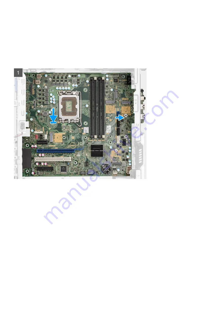
The following images indicate the location of the system board and provide a visual representation of the installation procedure.
Removing and installing components
99
Summary of Contents for D31M
Page 6: ...Chapter 6 Getting help and contacting Dell 123 6 Contents ...
Page 55: ...Removing and installing components 55 ...
Page 58: ...58 Removing and installing components ...
Page 96: ...96 Removing and installing components ...
Page 100: ...100 Removing and installing components ...


