background image

Interposer module

Removing the interposer module

Prerequisites

1. Follow the procedure in 

before working inside your computer

.

2. Remove the 

side cover

.

3. Remove the 

top cover (side bezel)

4. Remove the 

front bezel

.

5. Remove the 

fan assembly

.

NOTE:

 This step is valid for system configuration that is shipped with 80 W CPU.

6. Remove the 

riser card

.

About this task

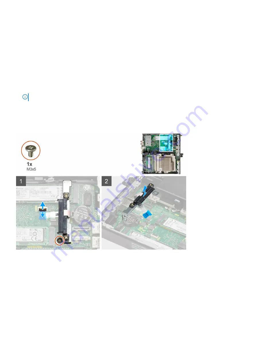
The following images indicate the location of the interposer module and provide a visual representation of the removal
procedure.

Steps

1. Flip open the actuator and disconnect the SATA FPC cable from the system board.
2. Loosen and remove the single screw (M3x5) securing the interposer module to the system board.

Installing the interposer module

Prerequisites

If you are replacing a component, remove the existing component before performing the installation procedure.

Disassembly and reassembly

63

Summary of Contents for D16S

Page 1: ...Dell Precision 3240 Compact Service Manual Regulatory Model D16S Regulatory Type D16S001 August 2020 Rev A00 ...

Page 2: ...ential damage to hardware or loss of data and tells you how to avoid the problem WARNING A WARNING indicates a potential for property damage personal injury or death 2020 Dell Inc or its subsidiaries All rights reserved Dell EMC and other trademarks are trademarks of Dell Inc or its subsidiaries Other trademarks may be trademarks of their respective owners ...

Page 3: ...ents of your system 17 Chapter 4 Disassembly and reassembly 20 Recommended tools 20 Screw List 20 SMA antenna 21 Removing the SMA antenna 21 Installing the SMA antenna 22 Side cover 23 Removing the side cover 23 Installing the side cover 25 Top Cover side bezel 26 Removing the top cover side bezel 26 Installing the top cover side bezel 28 Front bezel 29 Removing the front bezel 29 Installing the f...

Page 4: ...tate drive 52 Optional IO card 53 Removing the optional I O card 53 Installing the optional I O card 54 Coin cell battery 56 Removing the coin cell battery 56 Installing the coin cell battery 57 Heat sink 58 Removing the heat sink 58 Installing the heat sink 60 Interposer module 63 Removing the interposer module 63 Installing the interposer module 63 Processor 64 Removing the processor 64 Installi...

Page 5: ...ck RTC Reset 82 Dell SupportAssist Pre boot System Performance Check diagnostics 82 Running the SupportAssist Pre Boot System Performance Check 83 Diagnostic LED behavior 83 Diagnostic error messages 84 WiFi power cycle 87 Chapter 6 Getting help and contacting Dell 88 Contents 5 ...

Page 6: ...www dell com regulatory_compliance CAUTION Before touching anything inside your computer ground yourself by touching an unpainted metal surface such as the metal at the back of the computer While you work periodically touch an unpainted metal surface to dissipate static electricity which could harm internal components CAUTION When you disconnect a cable pull it by its connector or its pull tab not...

Page 7: ...r skin and ensure that you remove all jewelry such as watches bracelets or rings prior to bonding yourself and the equipment Electrostatic discharge ESD protection ESD is a major concern when you handle electronic components especially sensitive components such as expansion cards processors memory DIMMs and system boards Very slight charges can damage circuits in ways that may not be obvious such ...

Page 8: ...est once per week A wrist strap tester is the best method for doing this test If you do not have your own wrist strap tester check with your regional office to find out if they have one To perform the test plug the wrist strap s bonding wire into the tester while it is strapped to your wrist and push the button to test A green LED is lit if the test is successful a red LED is lit and an alarm soun...

Page 9: ...sure that no stray screws remain inside your computer 2 Connect any external devices peripherals or cables you removed before working on your computer 3 Replace any media cards discs or any other parts that you removed before working on your computer 4 Connect your computer and all attached devices to their electrical outlets 5 Turn on your computer Working on your computer 9 ...

Page 10: ... device to go into standby without needing to refresh its memory Deep power down mode is expected to reduce standby power consumption by 40 to 50 percent DDR4 Details There are subtle differences between DDR3 and DDR4 memory modules as listed below Key notch difference The key notch on a DDR4 module is in a different location from the key notch on a DDR3 module Both notches are on the insertion ed...

Page 11: ... interface N A Unified Memory Architecture UMA Graphics level 10th Generation Intel Comet Lake Xeon W series GT2 UHD P630 Estimated Maximum Power Consumption TDP 45 W included in the CPU power Maximum color depth 24 non HDR 30 HDR bit per pixel Maximum vertical refresh rate Up to 60 Hz depending on resolution Intel UHD graphics 630 Table 2 Intel UHD 630 graphics specifications Description Specific...

Page 12: ... 1x 5120x2880 60Hz Graphics APIs Shader Model 5 1 OpenGL 4 5 DirectX 12 0 Vulkan 1 0 Compute APIs CUDA DirectCompute OpenCL NVIDIA Quadro P620 Table 4 NVIDIA Quadro P620 specifications Description Values Graphics memory 2 GB GDDR5 Bus type PCIe x16 Gen 3 Memory Interface 128 bit Clock Speeds 1266 MHz graphics core min at P0 4012 MHz memory GPU base clock 1266 MHz min at P0 Estimated Maximum Power ...

Page 13: ...ed Up to four displays System management features Dell commercial systems come with a number of systems management options that are included by default for In Band management with the Dell Client Command Suite In Band management is when the system has a functional operating system and the device is connected to a network so that it can be managed The Dell Client Command Suite of tools can be lever...

Page 14: ... BIOS The updates are then delivered seamlessly to end users using the customer s systems management infrastructure that is consuming the catalog like SCCM Dell Command vPro Out of Band console Extends hardware management to systems that are offline or have an un reachable Operating System Dell exclusive features Dell Command Integration Suite for System Center Integrates all the key components of...

Page 15: ...Speed USB mode commonly known as USB 2 0 and 1 1 respectively the slower modes still operate at 480 Mbps and 12 Mbps respectively and are kept to maintain backward compatibility USB 3 2 Gen 1 achieves the much higher performance by the technical changes below An additional physical bus that is added in parallel with the existing USB 2 0 bus refer to the picture below USB 2 0 previously had four wi...

Page 16: ...Speed USB 3 2 Gen 1 products External Desktop USB Hard Drives Portable USB Hard Drives USB Drive Docks Adapters USB Flash Drives Readers USB Solid state Drives USB RAIDs Optical Media Drives Multimedia Devices Networking USB Adapter Cards Hubs Compatibility The good news is that USB 3 2 Gen 1 has been carefully planned from the start to peacefully co exist with USB 2 0 First of all while USB 3 2 G...

Page 17: ...3 Major components of your system 17 ...

Page 18: ...Major components of your system 18 Major components of your system ...

Page 19: ...emory modules 12 Interposer module 13 Solid state drive 14 Hard drive assembly NOTE Dell provides a list of components and their part numbers for the original system configuration purchased These parts are available according to warranty coverages purchased by the customer Contact your Dell sales representative for purchase options Major components of your system 19 ...

Page 20: ...at blade screwdriver Screw List The following table shows the screw list and the image of the screws Table 7 Screw list Component Screw type Quantity Image Top cover 6x32 Thumbscrew 1 M 2 2230 2280 Solid state drive M2x3 5 1 1 optional second solid state drive WLAN card M2x3 5 1 I O module optional M3x3 2 4 20 Disassembly and reassembly ...

Page 21: ...er card M3x5 2 SMA antenna Removing the SMA antenna Prerequisites 1 Follow the procedure in before working inside your computer About this task The following image indicates the location of the SMA antenna and provides a visual representation of the removal procedure Disassembly and reassembly 21 ...

Page 22: ... 3 Remove the SMA antenna from the system unit Installing the SMA antenna Prerequisites If you are replacing a component remove the existing component before performing the installation procedure About this task The following image indicates the location of the SMA antenna and provides a visual representation of the installation procedure 22 Disassembly and reassembly ...

Page 23: ...e Next steps 1 Follow the procedure in after working inside your computer Side cover Removing the side cover Prerequisites 1 Follow the procedure in before working inside your computer NOTE Ensure that you remove the security cable from the security cable slot if applicable About this task The following images indicate the location of the side cover and provide a visual representation of the remov...

Page 24: ...Steps 1 Loosen the thumbscrew 6x32 that secures the side cover to the system 24 Disassembly and reassembly ...

Page 25: ... the side cover Prerequisites If you are replacing a component remove the existing component before performing the installation procedure About this task The following image indicates the location of the side cover and provides a visual representation of the installation procedure Disassembly and reassembly 25 ...

Page 26: ...rking inside your computer Top Cover side bezel Removing the top cover side bezel Prerequisites 1 Follow the procedure in before working inside your computer NOTE Turn the optional SMA antenna downwards or remove it for convenient sliding of the top cover side bezel About this task The following image indicates the location of the top cover side bezel and provides a visual representation of the re...

Page 27: ...Steps 1 Slide the top cover side bezel towards the back of the system unit 2 Lift the top cover side bezel away from the system unit Disassembly and reassembly 27 ...

Page 28: ...g a component remove the existing component before performing the installation procedure About this task The following images indicate the location of the top cover side bezel and provide a visual representation of the installation procedure 28 Disassembly and reassembly ...

Page 29: ...iding back the top cover side bezel on the chassis 1 Follow the procedure in after working inside your computer Front bezel Removing the front bezel Prerequisites 1 Follow the procedure in before working inside your computer 2 Remove the side cover 3 Remove the top cover side bezel About this task The following image indicates the location of the front bezel and provides a visual representation of...

Page 30: ...talling the front bezel Prerequisites If you are replacing a component remove the existing component before performing the installation procedure About this task The following image indicates the location of the front bezel and provides a visual representation of the installation procedure 30 Disassembly and reassembly ...

Page 31: ... in after working inside your computer Hard drive assembly Removing the hard drive assembly Prerequisites 1 Follow the procedure in before working inside your computer 2 Remove the side cover 3 Remove the top cover side bezel 4 Remove the front bezel About this task The following images indicate the location of the hard drive assembly and provide a visual representation of the removal procedure Di...

Page 32: ...d drive assembly from the system NOTE Note the orientation of the hard drive so that you can replace it correctly Removing the hard drive bracket Prerequisites 1 Follow the procedure in before working inside your computer 2 Remove the side cover 3 Remove the top cover side bezel 4 Remove the front bezel 5 Remove the 2 5 in hard drive assembly 32 Disassembly and reassembly ...

Page 33: ... the bracket from the slots on the drive 2 Lift the hard drive out of the bracket Installing the hard drive bracket Prerequisites If you are replacing a component remove the existing component before performing the installation procedure About this task The following image indicates the location of the hard drive bracket and provides a visual representation of the installation procedure Disassembl...

Page 34: ...t bezel 3 Install the top cover side bezel 4 Install the side cover 5 Follow the procedure in after working inside your computer Installing the 2 5 in hard drive assembly Prerequisites If you are replacing a component remove the existing component before performing the installation procedure About this task The following image indicates the location of the hard drive assembly and provides a visual...

Page 35: ... release tabs clicks into place Next steps 1 Install the front bezel 2 Install the top cover side bezel 3 Install the side cover 4 Follow the procedure in after working inside your computer WLAN card Removing the WLAN card Prerequisites 1 Follow the procedure in before working inside your computer 2 Remove the side cover Disassembly and reassembly 35 ...

Page 36: ... Remove the M2x3 5 screw that secures the WLAN card bracket to the system board 2 Slide and lift the WLAN card bracket away from the WLAN card 3 Disconnect the antenna cables from the WLAN card 4 Slide and remove the WLAN card from the connector on the system board Installing the WLAN card Prerequisites If you are replacing a component remove the existing component before performing the installati...

Page 37: ...Antenna cable color scheme Connectors on the wireless card Antenna cable color Silkscreen marking Main White MAIN white triangle Auxiliary Black AUX black triangle 2 Place the WLAN card bracket to secure the antenna cables 3 Align the notch on the WLAN card with the tab on the WLAN card slot Insert the WLAN card into the connector on the system board 4 Replace the M2x3 5 screw to secure the WLAN c...

Page 38: ...ver side bezel 4 Remove the front bezel About this task The following images indicate the location of the speaker and provide a visual representation of the removal procedure Steps 1 Disconnect the speaker cable from the system board 2 Press the release tab and lift the speaker along with the cable from the system board Installing the speaker Prerequisites If you are replacing a component remove t...

Page 39: ...the front bezel 2 Install the top cover side bezel 3 Install the side cover 4 Follow the procedure in after working inside your computer Fan assembly Removing the fan assembly Prerequisites 1 Follow the procedure in before working inside your computer 2 Remove the side cover 3 Remove the top cover side bezel 4 Remove the front bezel About this task The following images indicate the location of the...

Page 40: ... the fan cable from the connector on the system board Lift the fan assembly out of the system Installing the fan assembly Prerequisites If you are replacing a component remove the existing component before performing the installation procedure About this task The following images indicate the location of the fan assembly and provide a visual representation of the removal procedure 40 Disassembly a...

Page 41: ... it on the system up side down until it clicks into place NOTE Route the speaker cable through the routing guides on the fan assembly Next steps 1 Install the front bezel 2 Install the top cover side bezel 3 Install the side cover 4 Follow the procedure in after working inside your computer Disassembly and reassembly 41 ...

Page 42: ...mage to the memory module hold the memory module by the edges Do not touch the components on the memory module Steps 1 Pull the securing clips from the memory module until the memory module pops up 2 Slide and remove the memory module from the memory module slot Installing the memory modules Prerequisites If you are replacing a component remove the existing component before performing the installa...

Page 43: ...er side bezel 4 Install the side cover 5 Follow the procedure in after working inside your computer Riser card Removing the riser card Prerequisites 1 Follow the procedure in before working inside your computer 2 Remove the side cover 3 Remove the top cover side bezel 4 Remove the front bezel 5 Remove the fan assembly NOTE This step is valid for system configuration that is shipped with 80 W CPU A...

Page 44: ...ard Installing the riser card Prerequisites If you are replacing a component remove the existing component before performing the installation procedure About this task The following image indicates the location of the riser card and provides a visual representation of the installation procedure 44 Disassembly and reassembly ...

Page 45: ...he riser card to the system chassis Next steps 1 Install the fan assembly NOTE This step is valid for system configuration that is shipped with 80 W CPU 2 Install the front bezel 3 Install the top cover side bezel 4 Install the side cover 5 Follow the procedure in after working inside your computer Disassembly and reassembly 45 ...

Page 46: ...emove the top cover side bezel 4 Remove the front bezel 5 Remove the fan assembly NOTE This step is valid for system configuration that is shipped with 80 W CPU 6 Remove the riser card About this task The following images indicate the location of the Dell Ultra Speed Drive and provide a visual representation of the removal procedure 46 Disassembly and reassembly ...

Page 47: ... to the Dell Ultra Speed Drive 5 Remove the standoff nut from the SSD 6 Slide the SSD out of the M 2 slot on the Dell Ultra Speed Drive Installing the Dell Ultra Speed Drive Prerequisites If you are replacing a component remove the existing component before performing the installation procedure About this task The following image indicates the location of the Dell Ultra Speed Drive and provides a ...

Page 48: ...48 Disassembly and reassembly ...

Page 49: ...n assembly NOTE This step is valid for system configuration that is shipped with 80 W CPU 3 Install the front bezel 4 Install the top cover side bezel 5 Install the side cover 6 Follow the procedure in after working inside your computer Graphics card Removing the graphics card Prerequisites 1 Follow the procedure in before working inside your computer 2 Remove the side cover 3 Remove the top cover...

Page 50: ...he riser card Installing the graphics card Prerequisites If you are replacing a component remove the existing component before performing the installation procedure About this task The following image indicates the location of the graphics card and provides a visual representation of the installation procedure 50 Disassembly and reassembly ...

Page 51: ...til it clicks into place Next steps 1 Install the riser card 2 Install the fan assembly NOTE This step is valid for system configuration that is shipped with 80 W CPU 3 Install the front bezel 4 Install the top cover side bezel 5 Install the side cover 6 Follow the procedure in after working inside your computer Disassembly and reassembly 51 ...

Page 52: ...the riser card 7 Remove the hard drive assembly About this task The following images indicate the location of the solid state drive and provide a visual representation of the removal procedure Steps 1 Remove the screw M2x3 5 that secures the solid state drive to the system board 2 Slide and lift the solid state drive off the system board Installing the M 2 2280 PCIe solid state drive Prerequisites...

Page 53: ...tate drive to the system board Next steps 1 Install the hard drive assembly 2 Install the riser card 3 Install the fan assembly NOTE This step is valid for system configuration that is shipped with 80 W CPU 4 Install the front bezel 5 Install the top cover side bezel 6 Install the side cover 7 Follow the procedure in after working inside your computer Optional IO card Removing the optional I O car...

Page 54: ...module to the system chassis NOTE The screw type differs with the kind of I O module used 2 Slide and remove the optional I O card from its slot in the chassis 3 Disconnect the cable that connects the optional I O card to the system board 4 Remove the I O card from the system unit Installing the optional I O card Prerequisites If you are replacing a component remove the existing component before p...

Page 55: ...About this task The following image indicates the location of the optional I O card and provides a visual representation of the installation procedure Disassembly and reassembly 55 ...

Page 56: ... two M3x3 screws to secure the optional I O card to the chassis NOTE The screw type differs with the kind of I O module used Next steps 1 Install the riser card 2 Install the hard drive assembly 3 Install the front bezel 4 Install the top cover side bezel 5 Install the side cover 6 Follow the procedure in after working inside your computer Coin cell battery Removing the coin cell battery Prerequis...

Page 57: ...provide a visual representation of the removal procedure Steps 1 Using a plastic scribe gently pry the coin cell battery out of the battery socket on the system board 2 Remove the coin cell battery out of the system Installing the coin cell battery Prerequisites If you are replacing a component remove the existing component before performing the installation procedure About this task The following...

Page 58: ... Install the top cover 4 Follow the procedure in after working inside your computer Heat sink Removing the heat sink Prerequisites 1 Follow the procedure in before working inside your computer 2 Remove the side cover 3 Remove the top cover side bezel 4 Remove the front bezel 5 Remove the fan assembly About this task The following images indicate the location of the heat sink and provide a visual r...

Page 59: ...Figure 4 Heat sink shipped with system configuration shipped with 65 W CPU Disassembly and reassembly 59 ...

Page 60: ...er 3 2 1 as printed on the heat sink 2 Lift the heat sink from the system board Installing the heat sink Prerequisites If you are replacing a component remove the existing component before performing the installation procedure About this task The following image indicates the location of the heat sink and provides a visual representation of the installation procedure 60 Disassembly and reassembly ...

Page 61: ...Figure 6 Heat sink shipped with system configuration shipped with 65 W CPU Disassembly and reassembly 61 ...

Page 62: ...the processor 2 Tighten the captive screws that secure the heat sink to the system board NOTE Tighten the screws in a sequential order 1 2 3 as printed on the heat sink Next steps 1 Install the fan assembly 2 Install the front bezel 3 Install the top cover side bezel 4 Install the side cover 5 Follow the procedure in after working inside your computer 62 Disassembly and reassembly ...

Page 63: ...the riser card About this task The following images indicate the location of the interposer module and provide a visual representation of the removal procedure Steps 1 Flip open the actuator and disconnect the SATA FPC cable from the system board 2 Loosen and remove the single screw M3x5 securing the interposer module to the system board Installing the interposer module Prerequisites If you are re...

Page 64: ... 1 Install the riser card 2 Install the fan assembly NOTE This step is valid for system configuration that is shipped with 80 W CPU 3 Install the front bezel 4 Install the top cover side bezel 5 Install the side cover 6 Follow the procedure in after working inside your computer Processor Removing the processor Prerequisites 1 Follow the procedure in before working inside your computer 2 Remove the...

Page 65: ... When removing the processor do not touch any of the pins inside the socket or allow any objects to fall on the pins in the socket 3 Gently lift the processor from the processor socket Installing the processor Prerequisites If you are replacing a component remove the existing component before performing the installation procedure About this task The following image indicates the location of the pr...

Page 66: ...ers are aligned at the same height If one or more corners of the processor are higher than the others the processor is not seated properly 2 When the processor is fully seated in the socket close the processor cover 3 Press down and push the release lever under the securing tab to lock it Next steps 1 Install the heat sink 2 Install the fan assembly 3 Install the front bezel 4 Install the top cove...

Page 67: ...6 Remove the hard drive assembly 7 Remove the solid state drive 8 Remove the WLAN card 9 Remove the speaker 10 Remove the fan assembly 11 Remove the memory modules 12 Remove the riser card 13 Remove the heat sink 14 Remove the interposer module About this task The following images indicate the location of the system board and provide a visual representation of the removal procedure Disassembly and...

Page 68: ...68 Disassembly and reassembly ...

Page 69: ... that secure the system board to the chassis 4 Lift the system board away from the chassis Installing the system board Prerequisites If you are replacing a component remove the existing component before performing the installation procedure About this task The following image indicates the location of the system board and provides a visual representation of the installation procedure Disassembly a...

Page 70: ...70 Disassembly and reassembly ...

Page 71: ...rive caddy support to the system board 4 Replace the three M3x4 screws and three 6 32 screws to secure the system board to the chassis Next steps 1 Install the interposer card 2 Install the heat sink 3 Install the riser card 4 Install the memory modules 5 Install the speaker 6 Install the fan assembly 7 Install the WLAN card 8 Install the solid state drive 9 Install the hard drive assembly 10 Inst...

Page 72: ... hard drive assembly 7 Remove the solid state drive 8 Remove the WLAN card 9 Remove the speaker 10 Remove the fan assembly 11 Remove the memory modules 12 Remove the riser card 13 Remove the heat sink 14 Remove the interposer module 15 Remove the system board About this task The following images indicate the location of the internal antenna and provide a visual representation of the removal proced...

Page 73: ...out this task The following image indicates the location of the Internal antenna and provides a visual representation of the installation procedure Steps 1 Align and replace the SMA antenna connector on the rear of the chassis and secure it using the single M3x3 screw to the chassis 2 Route the antenna cable along the metallic guide path on the chassis Next steps 1 Install the system board 2 Insta...

Page 74: ...ow the procedure in before working inside your computer 2 Remove the side cover 3 Remove the top cover 4 Remove the SMA antenna 5 Remove the front bezel 6 Remove the hard drive assembly 7 Remove the solid state drive 8 Remove the WLAN card 9 Remove the speaker 10 Remove the fan assembly 11 Remove the memory modules 12 Remove the riser card 13 Remove the heat sink 14 Remove the interposer module Ab...

Page 75: ...Disassembly and reassembly 75 ...

Page 76: ... that secure the system board to the chassis 4 Lift the system board away from the chassis Installing the system board Prerequisites If you are replacing a component remove the existing component before performing the installation procedure About this task The following image indicates the location of the system board and provides a visual representation of the installation procedure 76 Disassembl...

Page 77: ...Disassembly and reassembly 77 ...

Page 78: ...rive caddy support to the system board 4 Replace the three M3x4 screws and three 6 32 screws to secure the system board to the chassis Next steps 1 Install the interposer card 2 Install the heat sink 3 Install the riser card 4 Install the memory modules 5 Install the speaker 6 Install the fan assembly 7 Install the WLAN card 8 Install the solid state drive 9 Install the hard drive assembly 10 Inst...

Page 79: ...ayPort 1 4 Port HDMI 2 0b Port USB 3 2Gen 2 Type C Port with Alt mode 9 Processor socket 10 CPU Fan connector 11 Internal speaker connector 12 Two SODIMM DDR4 memory slots 13 M 2 2230 2280 SSD PCIe x4 connector Internal antenna Removing the Internal antenna Prerequisites 1 Follow the procedure in before working inside your computer 2 Remove the side cover 3 Remove the top cover 4 Remove the SMA an...

Page 80: ...images indicate the location of the internal antenna and provide a visual representation of the removal procedure Steps 1 Pry the metallic routing tabs and unroute the antenna cables from the chassis 2 Loosen and remove the single screw M3x3 securing the internal antenna to the chassis Installing the Internal antenna Prerequisites If you are replacing a component remove the existing component befo...

Page 81: ...he metallic guide path on the chassis Next steps 1 Install the system board 2 Install the interposer card 3 Install the heat sink 4 Install the riser card 5 Install the memory modules 6 Install the speaker 7 Install the fan assembly 8 Install the WLAN card 9 Install the solid state drive 10 Install the hard drive assembly 11 Install the front bezel 12 Install the SMA antenna 13 Install the top cov...

Page 82: ...as been retired on these models Start the RTC reset with the system powered off and connected to AC power Press and hold the power button for thirty 30 seconds The system RTC Reset occurs after you release the power button Dell SupportAssist Pre boot System Performance Check diagnostics About this task The SupportAssist diagnostics also known as system diagnostics performs a complete check of your...

Page 83: ...r Table 9 Diagnostic LED behavior Blinking pattern Problem description Suggested resolution Amber White 1 2 Unrecoverable SPI Flash Failure 2 1 CPU failure Run the Intel CPU diagnostics tools If problem persists replace the system board 2 2 System board failure included BIOS corruption or ROM error Flash latest BIOS version If problem persists replace the system board 2 3 No memory RAM detected Co...

Page 84: ...imeout waiting on ME to reply to HECI message If problem persists replace the system board 4 2 CPU Power Cable Connection Issue Diagnostic error messages Table 10 Diagnostic error messages Error messages Description AUXILIARY DEVICE FAILURE The touchpad or external mouse may be faulty For an external mouse check the cable connection Enable the Pointing Device option in the System Setup program BAD...

Page 85: ...ard drive and restart the computer Run the Hard Disk Drive tests in Dell Diagnostics HARD DISK DRIVE CONTROLLER FAILURE 0 The hard drive does not respond to commands from the computer Shut down the computer remove the hard drive and boot the computer from an optical drive Then shut down the computer reinstall the hard drive and restart the computer If the problem persists try another drive Run the...

Page 86: ...READ VALUE EXPECTING VALUE A memory module may be faulty or improperly seated Reinstall the memory module or if necessary replace it MEMORY WRITE READ FAILURE AT ADDRESS READ VALUE EXPECTING VALUE A memory module may be faulty or improperly seated Reinstall the memory module or if necessary replace it NO BOOT DEVICE AVAILABLE The computer cannot find the hard drive If the hard drive is your boot d...

Page 87: ...e and Time options TIMER CHIP COUNTER 2 FAILED A chip on the system board may be malfunctioning Run the System Set tests in Dell Diagnostics UNEXPECTED INTERRUPT IN PROTECTED MODE The keyboard controller may be malfunctioning or a memory module may be loose Run the System Memory tests and the Keyboard Controller test in Dell Diagnostics or Contact Dell X IS NOT ACCESSIBLE THE DEVICE IS NOT READY I...

Page 88: ...https www dell com support home app knowledgebase 2 Type the subject or keyword in the Search box 3 Click Search to retrieve the related articles Learn and get more information about your product Product specifications Operating system Setting up and using your product Data backup Troubleshooting and diagnostics Factory and system restore BIOS information Dell provides several online and telephone...

Page 89: ...er of the page 3 For customized support a Enter your system Service Tag in the Enter your Service Tag field b Click submit The support page that lists the various support categories is displayed 4 For general support a Select your product category b Select your product segment c Select your product The support page that lists the various support categories is displayed 5 For contact details of Del...

Reviews: