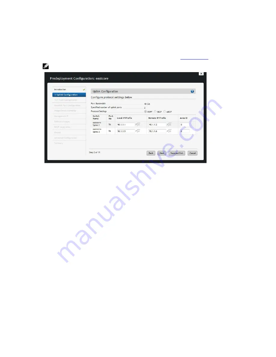
Pre-deployment – Step 1: Uplink Configuration (VLT)
The Uplink Configuration page displays the port bandwidth and the number of specified ports (read-only fields) entered
on the Fabric Name and Type and Port Specification screens. To configure the uplink protocol for the edge port uplinks
to the WAN, use the Uplink Configuration screen. For information about uplinks, see
VLT Terminology.
NOTE: For OSPF, the uplinks or interlinks must be in area 0.
Figure 20. Layer 2 VLT Uplink Configuration
To configure the uplink protocol for the edge port uplinks to the WAN:
1. Navigate to the Network >
Fabric Name
> Configure and Deploy screen.
2. From the Deploy Fabric pull-down menu, select the Pre-deployment Configuration option.
3. Navigate to the Uplink Configuration screen.
4. In the Protocol Settings, select a routing protocol (OSPF, IBGP, or eBGP) for the edge port uplinks. The Port
Specification screen specifies the number of uplinks.
The range of IP addresses belong to the /30 subnet is automatically populated by the AFM.
– For OSPF, for each specified uplink, enter the local IP address, remote neighbor IP address, and area ID. A
valid area ID area is 0 to 65535.
– For iBGP, for each specified uplink, enter the local IP address, remote neighbor IP address, local AS
number. For the AS number, enter a value from 1 to 4294967295.
– For eBGP, for each specified uplink, enter the local IP, remote neighbor IP address, local AS number, and
remote AS number. For the AS number, enter a value from 1 to 4294967295.
5. Click Next to go the VLT VLAN Configuration screen.
Pre-deployment - Step 2: Configuring a VLT VLAN
To specify a VLT VLAN to be applied to the Layer 2 fabric, use this screen. Specify at least one VLAN configuration.
59
Summary of Contents for Active Fabric Manager
Page 1: ...Active Fabric Manager Deployment Guide 1 5 ...
Page 8: ...8 ...
Page 10: ...10 ...
Page 14: ...Figure 2 Designing and Deploying a Fabric Flowchart 14 ...
Page 48: ...48 ...
Page 86: ...86 ...
Page 118: ...118 ...


