background image

Dell 2000FP LCD Monitor Service Guide 

                                                                                                                       Trouble Shooting 


Confidential 


1

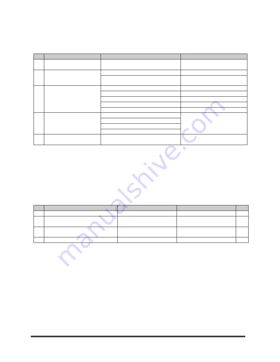
Categorizing the problem before troubleshooting 

Step  Condition 

Symptoms 

Troubleshooting category 

The monitor is connected to 
the adaptor 

All LEDs are on 

Abnormal LED troubleshooting 

LED is not working correctly 

Power not good troubleshooting 

The monitor is connected to 
appropriate signal source and 
the power button is pressed 

No splash screen / No video 

No video troubleshooting 

Picture on D-SUB is not good 

D-SUB troubleshooting 

Picture on DVI is not good 

DVI troubleshooting 

Picture on S-Video is not good 

S-Video troubleshooting 

Picture on Composite video is not good 

Composite video troubleshooting 

Picture is displaying but not 
good 

Picture on PIP is not good 

PIP troubleshooting 

Press menu key but there is no OSD 
Source selection key is not working 
Auto adjustment key is not working 

Picture is displaying normally  

OSD control keys are not working 

Keys not working troubleshooting 

No DDC 

PC system doesn’t detected the correct 
monitor name 

DDC troubleshooting 


Abnormal LED troubleshooting 

Normal operation 

Right after the adaptor is connected to the monitor, all the LEDs will turn on for less than 3 seconds and then 

turn off. 

Troubleshooting scope 

This troubleshooting applies to the case that all the LEDs are permanently on after the adaptor is connected. 

Step  Check item 

Yes 

No 

Note 

The LEDs are on permanently 

Step 2 

Beyond the scope 


IC113 is working and there is a valid 
clock output on pin 5 

Replace IC123 and go to Step 4  Step 3 


There is clock waveform on the 2 pins 
of Y103 

Replace IC113 
Go to step 4 

Replace Y103 
Go to step 4 


The LEDs are working normally 

Problem solved 

Contact ACM 

*Note: If the LEDs are not working, the image processor U1 and related ICs may not be working normally. 

Power not good troubleshooting 

Normal operation 

The LED on the AC adaptor is on. The monitor is connected correctly to the adaptor. After the power key is 

pressed, the power LED (green color) turns on and works normally. 

Troubleshooting scope 

Summary of Contents for 2000FP

Page 1: ...Appendix 3 Preset Mode Timings 8 Appendix 4 OSD Operation Procedures 9 Appendix 5 Special Indication 14 Appendix 6 Translation List 15 Appendix 7 EDID Content 15 Appendix 8 Power State Maximums 18 Appendix 9 LCD Module Specification 18 Appendix 10 Mechanical Specification 18 Appendix 11 Regulatories 19 Appendix 12 LCD Module Defects 20 Appendix 13 FOS Specifications Draft 21 Appendix 14 FOS Notes ...

Page 2: ...An LCD monitor an LCM with TMDS interface an I F board two control boards and an inverter A 15 pin D SUB cable and a DVI D signal cable A power adapter and a power cord Tilt and swivel base User manual CD ROM with E doc inf icm and cat including both analog digital registrations 2 Pacific Specification 2 1 GENERAL DESCRIPTION 2 1 1 Display Data Area with full white pattern 1 Horizontal 408 mm 2 Ve...

Page 3: ...gic 0 when the input absolute value is 0 8 V or less and logic 1 when the input absolute value is 2 3V or greater Impedance 2 2KOhm min pull down 3 Signal cable Analog Detachable shielded 2 0 meters 6 67 ft D SUB 15P male connector with blue connectors thumb screws and black color Digital Detachable DVI D white connectors 2 0 meters 6 67 ft and black color Video S VIDEO COMPOSITE video w o audio C...

Page 4: ...mode monitor is able to automatically adjust horizontal and vertical position phase and clock parameters to achieve the best image quality the image will be perfectly centered and noise exempted For UXGA Vs 60Hz this function can not be guaranteed Compatibility modes Auto adjustment ensures full specification for listed Preset Modes UXGA Vs 60Hz modes not included It is acceptable the auto adjustm...

Page 5: ...D Module Defects 3 Display Degradation Over the life of the product variation parameters defined in Appendix 12 will not vary 2 4 FRONT OF SCREEN 2 4 1 Min functional warm up time 3 mins 2 4 2 Specification 1 FOS associated with LCD See Appendix 13 FOS front of screen Specifications Module performance 2 Measurement conditions See Appendix 14 FOS Notes 3 FOS reliability Over the life of the product...

Page 6: ...oltage 90 to 264Vac RMS Universal input full range Input Frequency 47 63 Hz 90 to 264Vac Input Current Less than 1 7 ARMS Input voltage 90 Vac 60Hz Parameter must be reached within 3 seconds of turn on Inrush Current Less than 50A peak Input voltage 240Vac 50Hz at all phase cold start Input Fusing Fuse should be located internal to the adapter Fuse must be UL CUL approved Fuse value must no have t...

Page 7: ...2 DDC DATA SDA 13 HORIZONTAL SYNC H V 14 VERTICAL SYNC 15 DDC CLOCK SCL 1 5 6 10 11 15 15 pin D SUB female Digital input 30 pin DVI D connector Pin Signal assignment Pin Signal assignment 1 TMDS RX2 13 Floating 2 TMDS RX2 14 5V Power 3 TMDS Ground 15 Ground 4 Floating 16 Hot Plug Detect 5 Floating 17 TMDS RX0 6 DDC Clock 18 TMDS RX0 7 DDC Data 19 TMDS Ground 8 Floating 20 Floating 9 TMDS RX1 21 Fl...

Page 8: ...DEO connector PIN SIGNAL 1 GND 2 GND 3 LUMA 4 CHROMA G GND 3 4 2 1 G 4 pin S VIDEO female Video input II COMPOSITE video connector RCA jack Appendix 2 Labels and Markings Refer to RN 315 Appendix 3 Preset Mode Timings Resolution 60 Hz 70 Hz 75 Hz 640 480 P P 720 400 P 800 600 P P 1024 768 P P 1280 1024 P P 1600 1200 P ...

Page 9: ...2 1024 16 96 176 7 V Lines 78 750 75 029 800 768 1 3 28 1024 768 H Pixels 63 981 1688 1280 48 112 248 8 V Lines 108 000 60 020 1066 1024 1 3 38 1280 1024 H Pixels 79 976 1688 1280 16 144 248 9 V Lines 135 000 75 025 1066 1024 1 3 38 1280 1024 H Pixels 75 000 2160 1600 64 192 304 10 V Lines 162 000 60 000 1250 1200 1 3 46 1600 1200 Appendix 4 OSD Operation Procedures Key definitions There are 8 key...

Page 10: ...to display the Contrast and brightness adjustment menu For DVI D input the contrast adjustment is disabled Push the button to increase the contrast push the button to decrease the contrast min 0 max 100 Main menu Press MENU key to enter OSD main menu as figured below The OSD main menu has 8 items including Exit Positioning Image Settings Color Settings OSD Settings Language Factory Reset and PIP T...

Page 11: ...s in the main menu and press MENU to enter Image Setting sub menu Use or to switch among Auto Adjust Pixel Clock Phase Sharpness Scaling and Image Source functions When the selected item is highlighted the function is activated then you can press or to adjust the Auto Adjust Pixel Clock Phase Sharpness Scaling and Image Source functions Auto Adjust Press to start Auto Adjust function Pixel Clock P...

Page 12: ...SITE video input the color settings adjust the Hue Tint and Saturation function User Preset Press to adjust the value of R G and B separately Press Menu to return to the main menu OSD Settings Use or to select Horizontal Position Vertical Position OSD Hold Time and OSD Lock Horizontal Position Press to adjust the horizontal position of the OSD and press Menu to return to the previous OSD page Vert...

Page 13: ...Setting Color Setting and All setting and then press Menu to execute PIP Settings The function of PIP Settings is to set the Picture In Picture window Press or to select PIP Source PIP Size PIP Bright PIP Contr Hue Tint Saturation PIP Hor Pos or PIP Ver Pos and press and to adjust the item selected PIP Source Use to select input sources from S VIDEO and COMPOSITE Or Off to turn off PIP window Pres...

Page 14: ...PIP window Press Menu to return to the main menu PIP Hor Position Press to adjust the PIP window position horizontally Press Menu to return to the main menu PIP Ver Position Press to adjust the PIP window position vertically Press Menu to return to the main menu Appendix 5 Special Indication Self Test Feature Check STFC The floating Dell Self Test Feature Check dialog will appear on the screen aga...

Page 15: ...message of In Power Save Mode before entering the DPMS mode Appendix 6 Translation List TBD Appendix 7 EDID Content D SUB port Item Byte Description Data Hex Remarks HEADER 8 00 FF FF FF FF FF FF 00 2 Mfg Name 10 AC DELL 2 Product Code 02 A0 2000FP 4 Serial Number varies 34 33 32 31 4321 1 Mfg week varies 14 20th week Vendor Product ID 1 Mfg year varies 0B 2001 1 Version 01 1 EDID Version Revision...

Page 16: ... 01 01 01 01 01 01 01 01 01 01 Unused Detailed Timing Description 18 Detailed Timing Preferred timing mode 48 3F 40 30 62 B0 32 40 40 C0 13 00 6F 13 11 00 00 1E 1600 1200 60Hz Monitor Descriptor 18 Serial No 00 00 00 FF 00 30 30 33 30 50 39 37 52 31 32 33 34 0A Serial No 0030P 97R 1234 18 Monitor Name 00 00 00 FC 00 44 45 4C 4C 20 32 30 30 30 46 50 0A 20 DELL 2000FP 18 Range Limit 00 00 00 FD 00 3...

Page 17: ...24 768 60 Y 1024 768 70 N 1024 768 75 Y 1 Timing II 4B 1280 1024 75 Y Established Timings 1 Mfg reserved 00 Not used 2 ID 1 81 80 1280 1024 60Hz 2 ID 2 A9 40 1600 1200 60Hz Standard timing 10 ID 3 4 5 6 7 and 8 01 01 01 01 01 01 01 01 01 01 01 01 Unused Detailed Timing Description 18 Detailed Timing Preferred timing mode 48 3F 40 30 62 B0 32 40 40 C0 13 00 6F 13 11 00 00 1E 1600 1200 60Hz Monitor ...

Page 18: ...467 8 W 361 0 H 32 0 D Surface treatment Hard coating 3H Anti glare treatment Backlight Operating Lifetime Brightness 50 30 000Hrs min Maximum starting time Under operation conditions 2 sec Appendix 10 Mechanical Specification All plastics Resin ITEMS Specification Material GEC2800 Bayer FR2000 CHIEL NH 1000T Texture ACM standard UV 1 Heat Defection Temp 80 C Flame Retardant Pkg Triarylphosphate e...

Page 19: ...r or not the end user would consider the flaw s objectionable During this inspection only visual qualities are to be considered The unit shall exhibit no objectionable defects under the following inspection time and viewing distance criteria Front panels Inspect for 10 seconds at viewing distance of 500 mm All other sides Inspect for 5 seconds each at a viewing distance of 500 mm The following ite...

Page 20: ...fect AQL 1 5 1 dot N 5 Adjacent 2 dots N 1 Adjacent 3 dots Not allowed Min distance L 15mm Bright dot Total amount of Bright dot N 5 1 dot N 10 Adjacent 2 dots N 2 Adjacent 3 dots Not allowed Min distance L 15mm Dark dot Total amount of Dark dot N 10 Dot defect Total N 10 Scratch linear type 0 01 W 0 1 0 3 L 7 0 N 4 Polarizer Dent circular type 0 2 D 0 5 N 4 Dot shape 0 2 D 0 5 N 4 Foreign Materia...

Page 21: ...è è 80 80 80 80 Degree 5 Response Time Tr 39 45 msec 6 Appendix 14 FOS Notes 1 Test conditions unless otherwise specified all measurement shall be made under the test conditions below Ambient illumination level dark 10 lux Ambient temperature 25 o C Warm up 30 minutes Input signal timing VESA UXGA 60Hz on video generator User control Brightness 90 Contrast 50 Color temperature Factory user preset ...

Page 22: ...the transition time of L1 relative luminance from white to black state from 90 to 10 see graph below TrD measures the transition time of L1 relative luminance from black to white state from 10 to 90 see graph below 100 90 10 0 Optical Response white black white TrD TrR 7 White balance and chromaticity measured at Center position 8 Dark luminance at any point Specific conditions dark luminance is m...

Page 23: ...24 768 60Hz 48 363 60 004 7 1024 768 75Hz 60 023 75 029 8 1280 1024 60Hz 63 981 60 020 9 1280 1024 75Hz 79 976 75 025 10 1600 1200 60Hz 75 000 60 000 PIP function No Monitor settings Signal source Criteria 1 S Video with DVD NTSC 2 Main source D SUB or DVI displaying normally PIP source S Video and PIP size Large S Video with DVD PAL 3 Comp with DVD NTSC 4 Main source D SUB or DVI displaying norma...

Page 24: ...Hz 46 875 75 000 6 1024 768 60Hz 48 363 60 004 7 1024 768 75Hz 60 023 75 029 8 1280 1024 60Hz 63 981 60 020 9 1280 1024 75Hz 79 976 75 025 10 1600 1200 60Hz 75 000 60 000 Press Auto Adjustment if needed Check if the picture is OK and no jitters are found Any noise on the picture will not be acceptable DVI port Connect DVI D signal Check the following preset timings with General pattern No Mode H V...

Page 25: ... Video S Video with DVD PAL 3 Comp with DVD NTSC 4 Main source Comp video Comp with DVD PAL DVD video is displaying normally Any noise will not be acceptable Default settings No Item Default values 1 Brightness 90 2 Contrast 50 3 Color temperature 6500K 4 Image scaling Fill 5 Language English 6 OSD hold time 20 Color temperatures Color temperature The x coordinate The y coordinate 9300K 283 30 297...

Page 26: ...i timing support High quality advanced scaling function Power on off indicator 4 input indication LEDs Universal power adapter 0 255 W 0 255 H mm dot pitch LCD panel PIP picture in picture feature Fancy OSD features 16 bit bitmap color for the splash screen 16 pallets out of 16 bits colors for the OSD icons Block diagram FP2036 consists of an LCD module with 6 lamps an Inverter an Interface board ...

Page 27: ...n Theory Confidential 2 Circuit operation theory Block diagram GPORT PW171 VPORT Single Link TMDS Video Decoder S VIDEO Flash Rom 8 Mbits Clock Generator TMDS Trans mitter UXGA 1600 1200 LCM 140MHz ADC 100MHz ADC Deinterlacer COMP DVI D D SUB Keypad RS232 ...

Page 28: ...RGB data are then converted and go to G Port of PW171 Notice that these digital data are wired ORed with the data from TFP401 TMDS receiver at DVI D port TMDS receiver TI TFP401 is used as a TMDS receiver The maximal pixel clock is 162MHz 1600 1200 60Hz 24 bit data dual pixel mode are decoded and go to G Port of PW171 These data are wired ORed with the data from 2 AD9884 s A D converters at D SUB ...

Page 29: ... Buck Converter D D D D G S S S 5 6 7 4 3 2 1 8 L703 C713 L701 D701 Q703 Q704 R714 R715 C712 Q705 R719 D703 C711 R733 R732 R731 R737 OPEN 16V 100U 68U RB060L 40 2N3904 2N3906 3 3K 22 16V 100U SI4431DY 1 1K 1 RB060L 40 16V 100U 2 7K 0 20K GND Fig 1 Fig 1 shows a typical Buck converter circuit Q705 is a switching device Q703 Q704 are a totem pole which gets enough ability to drive P MOS When pin4 of...

Page 30: ...marily for power supply control the TL1451AC contains an on chip 2 5V regulator two error amplifiers an adjustable oscillator two dead time comparators undervoltage lockout circuitry and dual common emitter output transistor circuits The uncommitted output transistors provide common emitter output capability for each controller The internal amplifiers exhibit a common mode voltage range from 1 04V...

Page 31: ...vice Guide Circuit Operation Theory Confidential 6 The feedback circuit is composed of two resistors They are R718 and R719 and feedback the DC level 1 25V with error signal C717 is a compensation capacitor and R726 is dummy load ...

Page 32: ......

Page 33: ......

Page 34: ......

Page 35: ......

Page 36: ......

Page 37: ......

Page 38: ......

Page 39: ......

Page 40: ......

Page 41: ......

Page 42: ......

Page 43: ......

Page 44: ... R 453K 1 2 CP1 C CP 1 2 CP2 C CP 1 2 R8 R 453K 1 2 R21 R 4 75K 1 2 CP5 C CP 1 2 CP6 C CP 1 2 R23 R 4 75K N30 N31 N34 N37 1 2 C27 C 475Z 0805 1 2 C18 C 475Z 0805 Vbri 1 2 C3 C 225K 1206 1 2 C10 C 105Z 0805 1 2 C9 C 105Z 0805 1 2 D4 D RLZ33B 1 2 D8 D RLZ33B 1 2 C11 C 475Z 0805 1 2 C8 C 475Z 0805 1 2 C21 C 27P 1808 N17 1 2 C23 C 27P 1808 N18 1 2 3 4 5 6 7 8 CN1 S8B PH SM3 TB 1 2 R25 R NC 1 2 4 3 5 8...

Page 45: ...l keys are not working Keys not working troubleshooting 5 No DDC PC system doesn t detected the correct monitor name DDC troubleshooting Abnormal LED troubleshooting Normal operation Right after the adaptor is connected to the monitor all the LEDs will turn on for less than 3 seconds and then turn off Troubleshooting scope This troubleshooting applies to the case that all the LEDs are permanently ...

Page 46: ... display is either normal when appropriate signal is connected or there will be pop up messages indicating Check Signal Cable In Power Save Mode or Cannot Display This Video Mode Troubleshooting scope This troubleshooting applies to the case that the power LED on the monitor turns on normally after the power key is pressed but there is no splash screen showing up and no display is showing Step Che...

Page 47: ... V sync paths 5 Check if G CLK clock signal is good at R917 Step 6 Check IC901 and IC107 circuit 6 Check if R G B input signal at pin 7 15 22 of IC907 and IC107 is good Check IC901 and IC107 circuit Check D SUB signal cable and connector CON101 DVI troubleshooting Normal operation The monitor supports up to UXGA 60Hz on the DVI port The image is displayed normally Troubleshooting scope This troubl...

Page 48: ...ports NTSC PAL SECAM formats on the Composite video port The video is displayed normally Troubleshooting scope This troubleshooting applies to the case that Check Signal Cable is working normally but the video on Composite video is not displaying correctly Step Check item Yes No Note 1 Current input source is Composite video Remove Composite video cable and see if the floating message Check Signal...

Page 49: ... some of the key functions are not working properly Step Check item Yes No Note 1 Check if the control board and wires are connected well Step 2 Fix the wires 2 Check if CON115 and CON109 are well connected with the wires Check IC120 circuit Fix the wires DDC troubleshooting Normal operation The monitor can be detected by Plug and Play Windows system Graphics cards normally need valid EDID data to...

Page 50: ......

Reviews: