


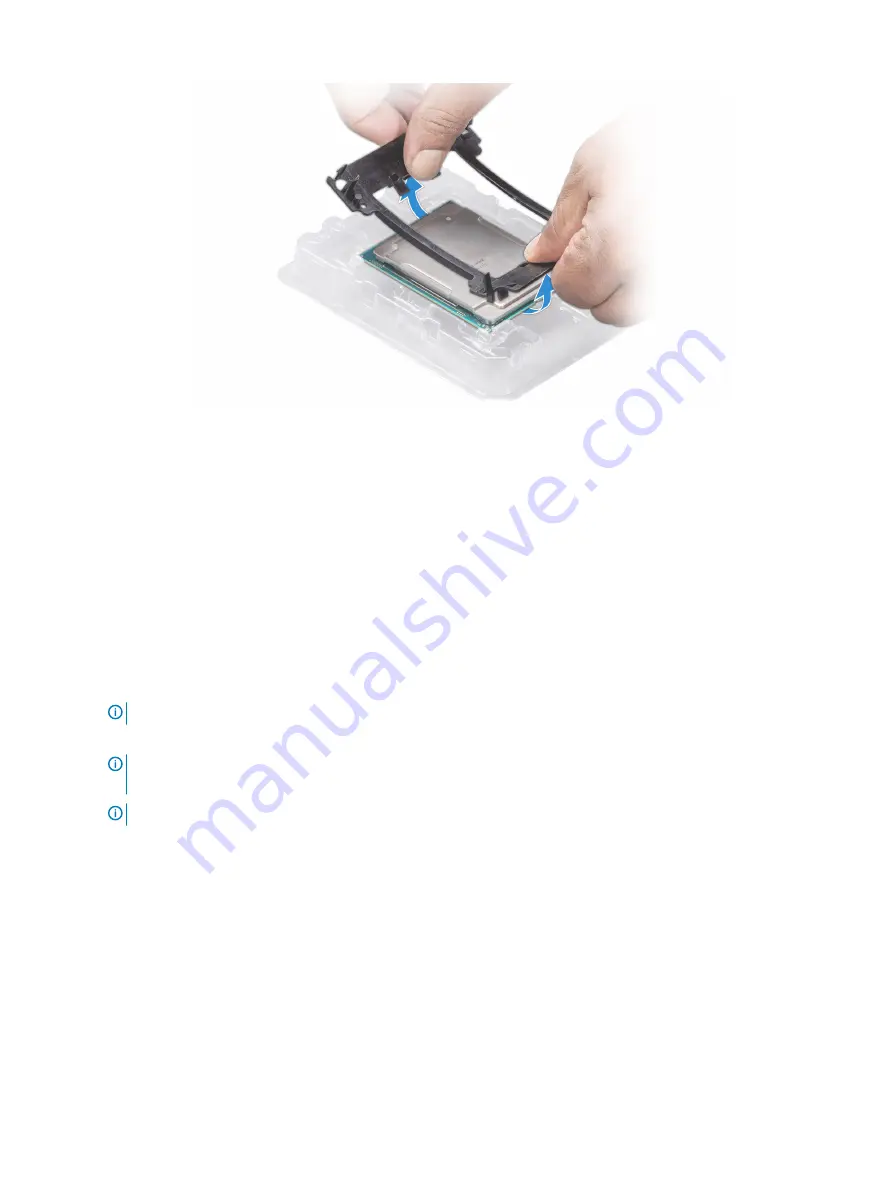
Figure 68. Removing the processor bracket
Next step
1
Install the processor into the processor and heat sink module.
Installing the processor into a processor and heat sink module
Prerequisite
Follow the safety guidelines listed in
Steps
1
Place the processor in the processor tray.
NOTE:
Ensure that the pin 1 indicator on the processor tray is aligned with the pin 1 indicator on the processor.
2
Flex the outer edges of the bracket around the processor ensuring that the processor is locked into the clips on the bracket.
NOTE:
Ensure that the pin 1 indicator on the bracket is aligned with the pin 1 indicator on the processor before placing
the bracket on the processor.
NOTE:
Ensure that the processor and the bracket are placed in the tray before you install the heat sink.
Installing and removing system components
121
Summary of Contents for PowerEdge T640
Page 23: ...Figure 16 Configuration and layout Dell EMC PowerEdge T640 overview 23 ...
Page 24: ...Figure 17 Electrical overview 24 Dell EMC PowerEdge T640 overview ...
Page 25: ...Figure 18 Memory information Dell EMC PowerEdge T640 overview 25 ...


