


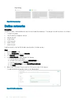


SmartFabric network configuration
The PowerEdge MX9002m management module hosts the OpenManage Enterprise Modular (OME-M) console. Creation and deployment
of SmartFabric topologies is facilitated using the OME-Modular console. SmartFabric is a web-based mechanism to create a reusable
networking template that can be applied to a PowerEdge MX7000 chassis, the IO modules (switches) and the compute sleds.
SmartFabric creates and configures the switches based on networking best practices. By selecting the topology, SmartFabric creates the
VLT domain and VLTi connections and creates the uplink LACP enabled link aggregations. It assigns VLANs to ports as either tagged or
untagged based on the networks that are created by the administrator through the SmartFabric interface.
NOTE:
For detailed instructions to deploy a SmartFabric, see
.
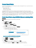
To deploy a SmartFabric, complete the following steps using the OME-Modular console:
1
Create chassis groups.
2
Create the networks to be used in the fabric.
3
Select IOMs and create the fabric that are based on the required physical topology.
4
Create uplinks from the fabric to the existing network and assign networks to those uplinks.
5
Deploy the appropriate server templates to the compute sleds.
Topics:
•
•
•
•
•
•
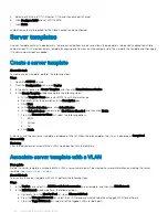
Create chassis groups
About this task
CAUTION:
The firmware version of the PowerEdge MX9002m management module is critical to the creation of a chassis group.
Ensure that the Management Module firmware matches the version listed in the
section.
Chassis groups are defined in the PowerEdge MX9002m management modules in the PowerEdge MX7000 chassis. Before a chassis group
can be created, the chassis PowerEdge MX9002m modules must be cabled together as shown in the following figure.
10
54
SmartFabric network configuration
Summary of Contents for PowerEdge MX7000
Page 1: ...Dell EMC VMware Cloud Foundation for PowerEdge MX7000 Deployment Guide ...
Page 8: ...Figure 1 Cloud Foundation deployment workflow 8 Overview ...
Page 27: ...Figure 19 Dual PowerEdge MX7000 enclosure configuration Physical layout 27 ...
Page 29: ...Figure 20 MX9002m Management module cabling Physical layout 29 ...
Page 30: ...Figure 21 Connectivity between FSE modules and FEM modules 30 Physical layout ...
Page 31: ...Figure 22 Uplinks to customer network environment Physical layout 31 ...
Page 42: ...Figure 25 MX9002m Management Module cabling 42 Networking requirements ...
Page 43: ...Figure 26 Connectivity between FSE modules and FEM modules Networking requirements 43 ...
Page 44: ...Figure 27 Uplinks to customer network environment 44 Networking requirements ...


