


a Click the fabric that was created.
b Click
Topology
.
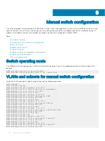
Create SmartFabric using MX9116n Fabric Switching Engine
IOMs
About this task
To create a SmartFabric using the OME-M console, perform the following steps:
Steps
1
Open the OME-M console.
2
From the
Devices
menu, click
Fabric
.
3
In the
Fabric
pane, click
Add Fabric
.
4
In the
Create Fabric
window, complete the following:
a Enter SmartFabric in the
Fabric Name
box.
b Optionally, enter the description in the
Description
box.
c Click
Next
.
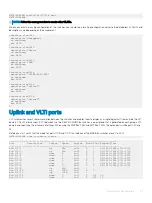
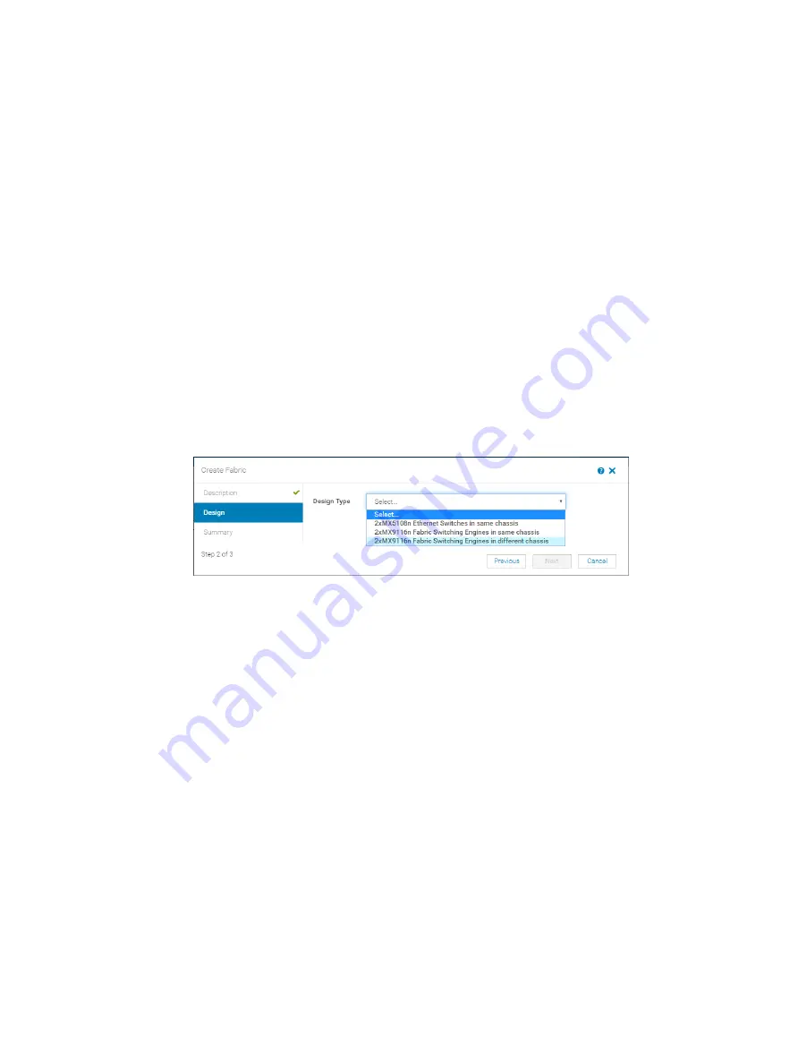
5
Based on your IOMs and number of chassis select from the
Design Type
list:
a 2x MX5108n Ethernet Switches in same chassis
b 2x MX9116n Fabric Switching Engines in same chassis
c 2x MX9116n Fabric Switching Engines in different chassis
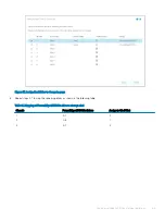
Figure 33. Create SmartFabric using MX9116n Fabric Switching Engine IOMs
6
From the
Chassis-X
list, select the first PowerEdge MX7000 chassis containing an MX9116n FSE.
7
From the
Switch-A
list, select
Slot-IOM-A1
.
8
From the
Switch-B
list, select
Slot-IOM-A2
.
9
Click
Next
.
10 On the
Summary
page, verify the proposed configuration, and then click
Finish
.
The fabric displays a health error which is resolved in the next section by adding uplinks to your fabric.
Configure uplinks
About this task
The newly created fabric requires uplinks to connect to the rest of the network. These uplinks are created as a single logical link to the
upstream network using the same Virtual Link Trunking (VLT). For more information, see the
section.
Perform the following steps to configure the uplinks:
Steps
1
From the
Devices
menu, click
Fabric
.
2
Click
SmartFabric
.
3
In the
Fabric Details
pane, click
Uplinks
.
4
Click
Add Uplinks
.
58
SmartFabric network configuration
Summary of Contents for PowerEdge MX7000
Page 1: ...Dell EMC VMware Cloud Foundation for PowerEdge MX7000 Deployment Guide ...
Page 8: ...Figure 1 Cloud Foundation deployment workflow 8 Overview ...
Page 27: ...Figure 19 Dual PowerEdge MX7000 enclosure configuration Physical layout 27 ...
Page 29: ...Figure 20 MX9002m Management module cabling Physical layout 29 ...
Page 30: ...Figure 21 Connectivity between FSE modules and FEM modules 30 Physical layout ...
Page 31: ...Figure 22 Uplinks to customer network environment Physical layout 31 ...
Page 42: ...Figure 25 MX9002m Management Module cabling 42 Networking requirements ...
Page 43: ...Figure 26 Connectivity between FSE modules and FEM modules Networking requirements 43 ...
Page 44: ...Figure 27 Uplinks to customer network environment 44 Networking requirements ...


