


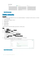


Figure 30. Group topology
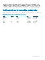
Define networks
Prerequisites
Networks or subnets should be defined to meet the Cloud Foundation requirements. The prerequisites to define networks are as follows:
1
Create chassis groups
2
Cloud Foundation management network
3
vMotion network
4
vSAN network
5
VXLAN network
6
Uplink1 network
7
Uplink2 network
To define networks using the OME-Modular console, perform the following steps:
Steps
1
Open the
OME-M
console.
2
From the
Configuration
menu, click
Networks
.
3
In the
Network
pane, click
Define
.
4
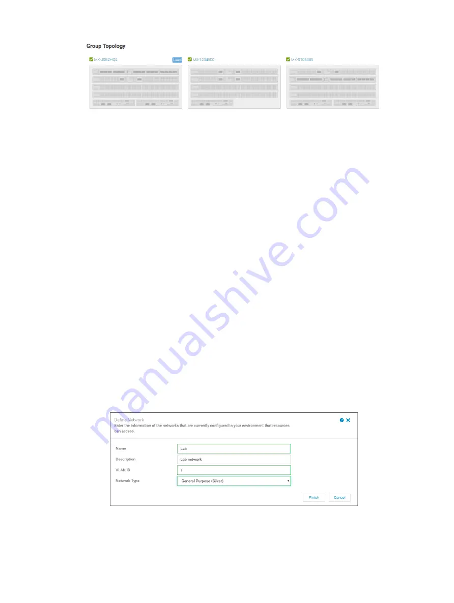
In the
Define Network
window, complete the following:
a Enter the name of the network.
b Optionally, enter the description in the
DESCRIPTION
box.
c Enter the value
1611
in the
VLAN ID
box.
d From the
Network Type
list, select
General Purpose (Bronze)
.
e Click
Finish
.
5
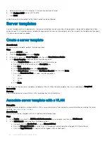
Repeat steps 1-4 to create the remaining five VLANs and any other VLANs required.
A sample completed configuration is shown in the following figure:
Figure 31. VLAN configuration
56
SmartFabric network configuration
Summary of Contents for PowerEdge MX7000
Page 1: ...Dell EMC VMware Cloud Foundation for PowerEdge MX7000 Deployment Guide ...
Page 8: ...Figure 1 Cloud Foundation deployment workflow 8 Overview ...
Page 27: ...Figure 19 Dual PowerEdge MX7000 enclosure configuration Physical layout 27 ...
Page 29: ...Figure 20 MX9002m Management module cabling Physical layout 29 ...
Page 30: ...Figure 21 Connectivity between FSE modules and FEM modules 30 Physical layout ...
Page 31: ...Figure 22 Uplinks to customer network environment Physical layout 31 ...
Page 42: ...Figure 25 MX9002m Management Module cabling 42 Networking requirements ...
Page 43: ...Figure 26 Connectivity between FSE modules and FEM modules Networking requirements 43 ...
Page 44: ...Figure 27 Uplinks to customer network environment 44 Networking requirements ...


