Delem DAC-360 Installation Manual Download Page 33

Delem

V0208, 2.7

All measured axis positions and their corresponding corrections can be entered in a table on 
the control.
To access the correction table, proceed as follows:

enter the machine parameters menu as described in chapter 1,

enter the parameters for the backgauge,

scroll to parameter 29, ‘Spindle correction table’,

press  ENTER.

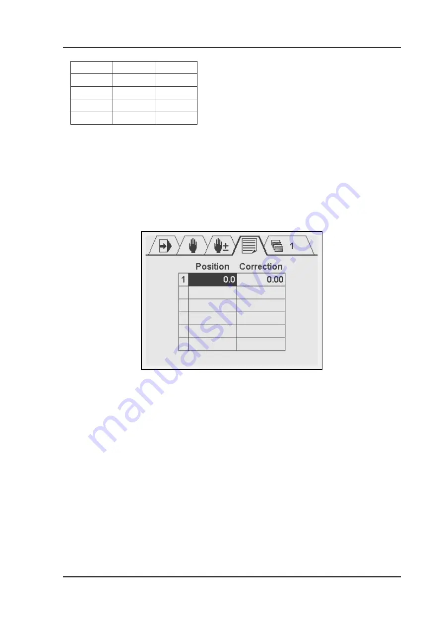
The following screen appears:

Each line consists of the line number, the axis position (Pos) and the necessary correction 
(Cor).
The table can be edited as follows:

Use the arrow keys to move up, down, left and right.

To add a row, go to the first column and press the ENTER key.

To delete a row, go to the first column of the previous row and press the Clear key. All 
rows after the current row will be deleted!

To enter a value, move to the required cell, type the value and press ENTER.

A maximum of 20 corrections can be programmed in the table.
For positions between the programmed positions, a correction computed through linear 
interpolation.

Xm

P

Cor

X1

P1

Cor1

X2

P2

Cor2

...

...

...

Xn

Pn

Cor n

Summary of Contents for DAC-360

Page 1: ...Delem Manual version V0208 DAC 360 Installation manual Version 1...

Page 2: ...nce with Delem s specifications The guarantee on the equipment is invalidated in the event of improper installation and or use of this equipment The General Terms and Conditions of Delivery of Delem s...

Page 3: ...chine parameter types 2 2 1 1 Menu 2 2 1 2 Control types 2 2 1 3 Spindle correction table 2 6 2 The machine parameters 2 8 2 1 General parameters 2 8 2 2 Backgauge control parameters 2 10 2 3 Angle co...

Page 4: ...V0208 0 4 1 3 Test functions 3 3 1 4 Service screens 3 3...

Page 5: ...efault retract 2 16 Enable CY 2 9 Enable display correction 2 12 Enable sheet position 2 32 Fixed angle 2 25 Gap material table 2 30 Gap reference table 2 29 Gap2 reference table 2 31 I gain 2 20 In P...

Page 6: ...V0407 0 6...

Page 7: ...Delem V0407 1 1 Part I Hardware description This section contains the hardware specifications of a Delem DAC 360 control...

Page 8: ...is a universal programmable control designed to control positioning of machine parts such as the backgauge control of an industrial shear The control is capable of controlling servo loop systems a on...

Page 9: ...ironmental conditions The following environment specification values are valid for a DAC 360 control Ambient temperature 5 50 C Storage temperature min 20 C max 70 C Relative humidity max 90 non conde...

Page 10: ...28 VDC 5W I O excluded Display LCD STN resolution 320 x 240 black white Interfaces 1 x Encoder max 1 MHz 1 x RS 232 I O 8 x Digital input 24V 16 x Digital output 24V 1 x analog output 0 10V 2 x analog...

Page 11: ...d with a set of connectors for various functions system I O encoder feedback communication The various connectors are discussed in the following sections Warning Connectors may not be plugged or unplu...

Page 12: ...he power supply and the analog output for axis movement Power supply 18 28 VDC 5W I O excluded Analog output 0 10V 10mA max The Analog connector CN19 provides several analog signals two analog outputs...

Page 13: ...CN3 Pins 17 24 Programmable Digital Outputs 8x Notes The sum of all output currents should not exceed 8A All digital outputs are short circuit proof I O power supply 24 V DC 20 8A max Digital Outputs...

Page 14: ...tion details Notes In case of 12VSE encoder connect pins 6 7 8 and 9 with eachother 9 pole SUBD female encoder interface power supply 5V DC 250 mA or 12V DC 200 mA possibilities 12 V single ended 5 V...

Page 15: ...07 1 9 4 Spare parts The following table gives an overview of the available spare parts for the DAC 360 control Number Description FRONT 360 Front panel DAC 360 DLCD 360 LCD screen D 7453 001 Mainboar...

Page 16: ...tics about the DAC 360 control 8062 901 Mounting dimensions 8062 912 Cables and connectors 8062 101 Connection diagram 8062 103 Connection diagram 8062 104 Connection diagram 8062 107 Connection diagr...

Page 17: ......

Page 18: ......

Page 19: ...8VDC POWER IN 0V A1 OUT 10V 10V A1 0V Not connected Not connected CN4 15P SUBD Female See drawing 8062 901 for mounting dimensions See drawing 8062 907 for default digital I O allocation 21 23 22 24 I...

Page 20: ...10V 10V A1 0V Not connected Not connected CN4 15P SUBD Female See drawing 8062 901 for mounting dimensions See drawing 8062 907 for default digital I O allocation 21 23 22 24 INPUTS OUTPUTS 10 POLE M...

Page 21: ...S OUTPUTS 6 POLE MALE POWER IN 24 28VDC POWER IN 0V A1 OUT 10V 10V A1 0V Not connected Not connected CN4 15P SUBD Female See drawing 8062 901 for mounting dimensions See drawing 8062 907 for default d...

Page 22: ...Female See drawing 8062 901 for mounting dimensions See drawing 8062 907 for default digital I O allocation 21 23 22 24 INPUTS OUTPUTS 10 POLE MALE 24V OUT 1 OUT 2 OUT 3 OUT 4 IN 5 IN 6 IN 7 IN 8 0V 2...

Page 23: ...OWER IN 24 28VDC POWER IN 0V A1 OUT 10V 10V A1 0V Not connected Not connected CN4 15P SUBD Female See drawing 8062 901 for mounting dimensions See drawing 8062 907 for default digital I O allocation 2...

Page 24: ...adjustment out EOS in case of combined potentiometer out EOC out FD DAC 360 pressure outputs S0 Controller Stopped Status S1 S2 S3 S4 S5 S1 S1 Positioning S2 Wait for ST low inp PEDAL S3 Wait for EOS...

Page 25: ...ped Status S1 S2 S3 S4 S5 S1 S1 Positioning S2 Wait for ST low out UDP S3 Wait for EOS S4 Wait for UDP inp ST S5 Wait for ST high out RDY in PEDAL out EOS out EOC out FD DAC 360 with timed stroke S0 C...

Page 26: ...ng int RetractEnable out FD inp R out X IP T8 T8 Retract hold int BusyRetract DAC 360 Retract Timing W ait for Retract S0 Controller Stopped Status S1 S2 S3 S7 S4 S6 S1 S1 Positioning S2 W ait for ST...

Page 27: ...Delem V0208 2 1 Part II Machine settings This section will describe the necessary settings of a DAC 360 control regarding machine settings...

Page 28: ...rsor bar to the correct menu and press ENTER Press the Stop button to exit a menu or to return to normal operation mode In the next chapter the machine parameters are explained The following sections...

Page 29: ...g the movement and especially at the end position Reduce the P gain again to the point where there was no oscillation Increase the I gain until you notice oscillation at the end position Reduce the I...

Page 30: ...epends on the known deceleration rate of the axis equipment If the BLS is not accurate enough to reach the programmed position the parameter Stop time T can be used for further fine tuning of the posi...

Page 31: ...to a high position the axis will move to the overrun position programmed position OR After that the axis starts moving in the opposite direction and positioning takes place When the difference betwee...

Page 32: ...position errors due to mechanical inaccuracies in the spindle If a spindle shows deviations then they should be measured systematically on certain setpoints From these setpoints a table with correcti...

Page 33: ...axis position Pos and the necessary correction Cor The table can be edited as follows Use the arrow keys to move up down left and right To add a row go to the first column and press the ENTER key To...

Page 34: ...he maximum sheet thickness the machine can cut Parameter 14 Maximum cutting length Range 0 0 15000 0 Unit mm Default 1000 0 Function The maximum length the machine can cut This setting will effect the...

Page 35: ...step repetition is not possible 1 CY enabled program step repetitions can be programmed Parameter 17 Number of FD functions Range 0 4 Unit Default 0 Function Program the number of available function...

Page 36: ...Range 0 1 Unit Default 0 Remark Only if Control Type 19 is set to 3 Function This parameter defines whether or not the speed of the axis can be programmed in user mode If enabled then in programming...

Page 37: ...avel speed when the arrow key is pressed continuously This parameter should be programmed as a percentage of the maximum speed Parameter 24 Decimal point position Range 0 2 Unit Default 1 Function 0 1...

Page 38: ...xis position is within the In Position tolerance 0 real actual values are shown 1 programmed value is shown when axis in position In both cases the value is highlighted when the axis is within the IP...

Page 39: ...he control counts every quadrant of one encoder cycle Example number of encoder pulses 50 pulse rev spindle pitch 2 mm rev results in F 50 2 4 100 counts mm Parameter 29 Spindle correction table Range...

Page 40: ...parameters will appear which need to be programmed Parameter 32 Reference search direction Range 0 1 Unit Default 1 Remark Only if Reference Search 31 is set to 1 Function Controls the direction of th...

Page 41: ...d at the programmed speed 34 in the programmed direction 32 until the control receives a signal from the RSD switch RSD input becomes low The control will stop movement and send the axis in the revers...

Page 42: ...high to low transition of the input ST which is the moment to start cutting When set to 0 the backgauge is only retracted when the R input becomes high Parameter 38 Minimum retract Range 0 0 9999 9 U...

Page 43: ...collision The output XSAFE is used to indicate the X axis status TRUE if the X axis is outside the zone X Safety zone FALSE if the X axis is inside the zone X Safety Zone Parameter 42 Spindle allowanc...

Page 44: ...e at overrun position before the axis starts positioning in the opposite direction Parameter 45 Maximum operating speed Range 1 9999 Unit mm s Default 200 Remark Only if Control type 21 is set to 3 Fu...

Page 45: ...rea defined by X Limit 46 The speed is programmed as a percentage of the maximum speed This speed setting is also used when the input LSX is active Parameter 48 Acceleration 0 to max Range 0 9999 Unit...

Page 46: ...top This rate of deceleration is used when normal operation is interrupted for instance when the stop button is pressed on the control or a forced stop has been generated Parameter 51 P gain Range 0 0...

Page 47: ...rake enable Range 0 1 Unit Default 0 Remark Only if Control type 19 is set to 1 or 2 Function Enable the brake output BRK This can be used to control an AC motor with brake 0 no brake signal 1 enable...

Page 48: ...ounts Default 10 Remark Only if Control type 19 is set to 1 or 2 Function Switch point from low speed to zero in the upcounting direction Parameter 58 Brake point high speed Range 0 9999 Unit counts D...

Page 49: ...pe 19 is set to 1 or 2 Function This is the output voltage for low speed movement in the negative direction This parameter must be programmed if a DC motor drive is controlled with the analog output I...

Page 50: ...e 19 is set to 2 Function This is the output voltage for high speed movement in the positive direction This parameter must be programmed if a 2 speed DC motor drive is controlled with the analog outpu...

Page 51: ...can be used to connect a frequency regulator See also chapter 1 about unipolar control Parameter 68 In Position tolerance Range 0 01 9 99 Unit mm Default 1 0 Function The in position IP output become...

Page 52: ...the tolerance and the output A_IP becomes high Parameter 72 Angle prestop positive Range 0 99 Unit AD value Default 0 Function Due to the inertia of the Angle system there can be some overshoot after...

Page 53: ...Default Function Press ENTER to open the screen with the angle reference table In this table the relation between the blade angle and the feedback voltage can be programmed Angle program a known angl...

Page 54: ...ed in the vertical column as a percentage of the maximum thickness parameter 13 Maximum thickness For various plate thickness values the required angle value can be programmed These setpoints can be p...

Page 55: ...restop before the Gap has reached position The Gap prestop positive must be programmed for Gap movement in the positive direction The value is programmed in AD points a converted digital value of the...

Page 56: ...adjustment procedure to find the correct AD values is similar to the procedure for angle values as described in the previous section Parameter 80 Gap material table Range Unit Default Function Press...

Page 57: ...l enable Range 0 1 Unit Default 0 Function Program control for a second gap unit Gap2 on or off 0 No gap control 1 Gap control In case of 1 the following I O is used digital outputs G2 and G2 analog i...

Page 58: ...handled by a timer At parameter 87 the maximum possible stroke length is programmed at parameter 88 the necessary time is pogrammed to reach this maximum stroke In a cutting step the stroke length is...

Page 59: ...le Parameter 89 Stroke time Range 0 9999 Unit msec Default 0 Remark This parameter must be programmed when stroke mode is set to 1 Function This is the time necessary to reach the maximum stroke lengt...

Page 60: ...0 10V The adjustment procedure to find the correct AD values is similar to the procedure for angle values as described in section 2 5 Parameter 91 Rotation offset Range 0 9999 Unit mm Default 0 Functi...

Page 61: ...rs Parameter 93 Main force enable Range 0 1 Unit Default 0 Function Enable or disable cutting force on the control 0 no control 1 cutting force control enabled Parameter 94 Cutting force factor Range...

Page 62: ...Unit msec Default 200 Function This parameter describes the ramp for the main force increase decrease It is programmed as the time in which the force output increases from minimum to maximum voltage P...

Page 63: ...delay before opening control is started An opening delay is useful to overcome the response time of the clamping system and or the pressure control system in case of force control In the timing diagra...

Page 64: ...efault 0 Function The time the main force output stays active for clamping Parameter 105 Clamping force enable Range 0 1 Unit Default 0 Function Enable or disable separate clamping force on the contro...

Page 65: ...8 Clamping reference table Range Unit Default Function Press ENTER to open a screen with the Clamping reference table In this table the relation between clamping force and control output voltage can b...

Page 66: ...only Example The example picture above shows an example of a possible mapping of output pins In the picture pins 5 8 are allocated for the movement of a 2 speed AC drive fast and slow in both directio...

Page 67: ...keys and keys to the necessary intersection press ENTER To erase a connection go to it with the cursor and press ENTER The connection will disappear The numbers 5 8 and 13 16 refer to the digital inpu...

Page 68: ...check the supported interval as indicated by RetractEnable EXS External Start Input to start the control X_RES Reset X Reset X position to 0 support decoiling KEY Program enable Signal to block or ena...

Page 69: ...G2 Gap2 close Reduce gap2 opening G1_OK Gap 1 OK Gap 1 control ready G1_IP Gap 1 in position Gap 1 in position G1 Gap open Increase gap opening G1 Gap close Reduce gap opening A_OK Angle control read...

Page 70: ...sition feedback of the Gap1 opening in case Gap system with position feedback is enabled AFB Angle feedback Feedback of angle value in case angle control is installed Code Name Description CF Cutting...

Page 71: ...e you should save your settings When the control is upgraded all settings are set back to default values After the upgrade you can restore your settings from the PC The PC and the control are connecte...

Page 72: ...lect a filename and a location for the file with control settings To load control settings into the control click the button Restore in the dialogue select the file with control settings that must be...

Page 73: ...t to factory default settings See the previous section for more information about back up and restore Make sure the necessary cables are connected and the DAC control is switched on To perform the upd...

Page 74: ...parameter menu See also chapter 1 741 Use this code to enter the diagnostic mode of the control See part III of this manual 123123 Use this code to reset the hours counter and stroke counter to zero e...

Page 75: ...is high S1 Positioning Not all axes are in position yet S2 Wait for ST low Waiting for STEP input falling edge S3 Wait for EOS Wait for EOS generated by potentiometer or BR S4 Wait for UDP Wait for UD...

Page 76: ...V0208 2 50...

Page 77: ...Delem V0407 3 1 Part III Diagnostic program To be able to test a DAC 360 control it has been equipped with a diagnostic program...

Page 78: ...f the axis is performed With the diagnostic program you have to be careful because all I O is controlled All digital and analog outputs can be activated for motor movement or relay switching 1 2 Test...

Page 79: ...puts accept voltages between 10V and 10V The voltage is indicated with 12 bit values between 4095 and 4095 Encoder Test the encoder input and the encoder counting Use the Ref field to check the encode...

Page 80: ...V0407 3 4 In this screen the status of all internal I O signals is shown In this screen the programmed and actual values of parameters is shown In this screen the status of all physical I O is shown...

Page 81: ...5 A program step can be started in order to view the I O behaviour In the service mode it is not possible to program parameters or I O Press the keys arrow down and arrow up to browse through the ser...

Page 82: ...V0407 3 6...

Reviews: