background image


Page 4 of 8

Tel.: (+45) 9614 9614 

Fax: (+45) 9614 9615 

E-mail: [email protected]


Functions and settings 

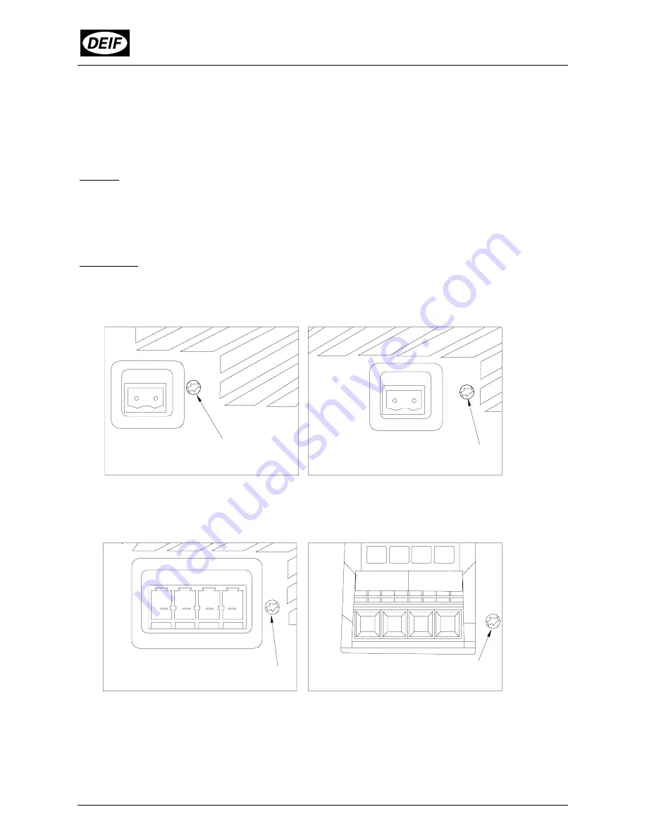
Besides the output terminals (secondary side) the DCP2 has a  trim potentiometer for 
setting of the output voltage. By means of an insulated slotted screwdriver or adjusting 
pin the output voltage can be set in the range 23.5-27.5V respectively 11.8-13.8V. 
 
Setting: 
Lower output voltage  =   Counterclockwise rotation 
Higher output voltage  =   Clockwise rotation  
 
The LED on the front indicates that the unit is operational. 
 
Illustration:  
Terminals of the secondary side and setting potentiometer for output voltage. 


DCP2-XX05 

DCP2-XX10 and -XX10/115V 


CAUTION: 

For DCP2-2420 and DCP2-2440 the plugs on the secondary side have two terminals 
for each pole (+/-). The current can be drawn by one single terminal for each pole. 
DEIF recommends to use both terminals for each pole to avoid any unnecessary 
heating of the connection. 
 

DCP2-2420 DCP2-2440


Setting pot

Setting pot

Setting pot

Setting pot

Summary of Contents for DCP2

Page 1: ...14 9615 Denmark E mail deif deif com DEIF A S Installation instructions Type DCP2 Battery chargers 4189320008D UK Easy installation DIN rail mounting Automatic recovery from overload conditions 5 10 20 40A types Switch mode power technology Extremely low ripple 100mV ...

Page 2: ...2420 20A typical current limit 25A DCP2 2440 40A typical current limit 45A Terminals DCP2 1205 1210 2405 2410 and 2410 115V Primary max 2 5 mm Secondary 2 5 mm DCP2 2420 Primary max 2 5 mm Secondary 4 0 mm DCP2 2440 Primary max 2 5 mm Secondary 10 0 mm Indication Green LED operating indication Housing Materials All plastic parts are self extinguishing to UL94 V0 DCP2 2440 is encapsulated in a meta...

Page 3: ...I Deg of protection IP20 Leakage current 0 75mA 47 63Hz line frequency DCP2 2420 3 phase supply and DCP2 2440 3 5mA Weight DCP2 1205 approx 0 8 kg DCP2 2405 approx 0 8 kg DCP2 1210 approx 1 2 kg DCP2 2410 approx 1 2 kg DCP2 2410 115V approx 1 2 kg DCP2 2420 approx 1 9 kg DCP2 2440 approx 3 6 kg ...

Page 4: ...rclockwise rotation Higher output voltage Clockwise rotation The LED on the front indicates that the unit is operational Illustration Terminals of the secondary side and setting potentiometer for output voltage DCP2 XX05 DCP2 XX10 and XX10 115V CAUTION For DCP2 2420 and DCP2 2440 the plugs on the secondary side have two terminals for each pole The current can be drawn by one single terminal for ea...

Page 5: ...P2 2440 Operating with a disconnected phase is not permissible Fuse DCP2 1205 2405 5 x 20 mm T3 15A 250V internal DCP2 1210 2410 2410 115V 5 x 20 mm T6 3A 250V internal DCP2 2420 5 x 20 mm T10A 250V internal DCP2 2420 2440 Three poles C fuse or motor circuit breaker Switch external setting 3A CE marking All variants of the DCP2 are CE marked to the EMC Directive and the Low Voltage Directive Howev...

Page 6: ... and 20A variants must be given by the local power supply authority of the place of installation of the DCP2 as stipulated by EN 61000 3 2 clause 4 In this case the entire CE marking provided by DEIF A S including to EN 61000 3 2 is valid The protective earth PE of the DCP2 must be connected to the protective earth of the switchboard Illustration Grid connection DCP2 XX05 DCP2 XX10 XX10 115V DCP2 ...

Page 7: ...Installation instructions DCP2 4189320008D UK Appendix Type Dimensions DCP2 1205 DCP2 1210 DCP2 2405 DCP2 2410 and 2410 115V 105 123 147 86 86 105 123 205 105 123 147 86 86 105 123 205 ...

Page 8: ...Page 8 of 8 Tel 45 9614 9614 Fax 45 9614 9615 E mail deif deif com Type Dimensions DCP2 2420 DCP2 2440 86 240 130 153 264 292 130 176 185 ...

Reviews: