background image

Dedicated Micros ©2009

11

D

V-IP RT

Point&go

Point&go enables an Oracle Dome camera to be controlled directly via the mouse. Click anywhere 

on the displayed image and the Oracle dome camera will centre on that point i.e. to pan the camera 

to the right, click on the right hand side of the displayed image. The Oracle dome will pan and set 

the clicked point as the centre of the new image.

Note:  To use Point&go, PTZ mode must be selected (if available). 
Note:  Oracle dome cameras can also be controlled using the Joystick / Directional Control 

Buttons on the DM KBC1 / KBC2 Keyboards.

Telemetry Command Options

Telemetry commands can be activated directly via the Telemetry Command symbols. To access the 

modes and options featured below, roll the USB mouse over the camera symbols displayed in the 

upper right of the screen. The modes available will depend on the camera type being accessed.

Note:  The symbols shown below will only be displayed if viewing via a local monitor and not  

the webpages

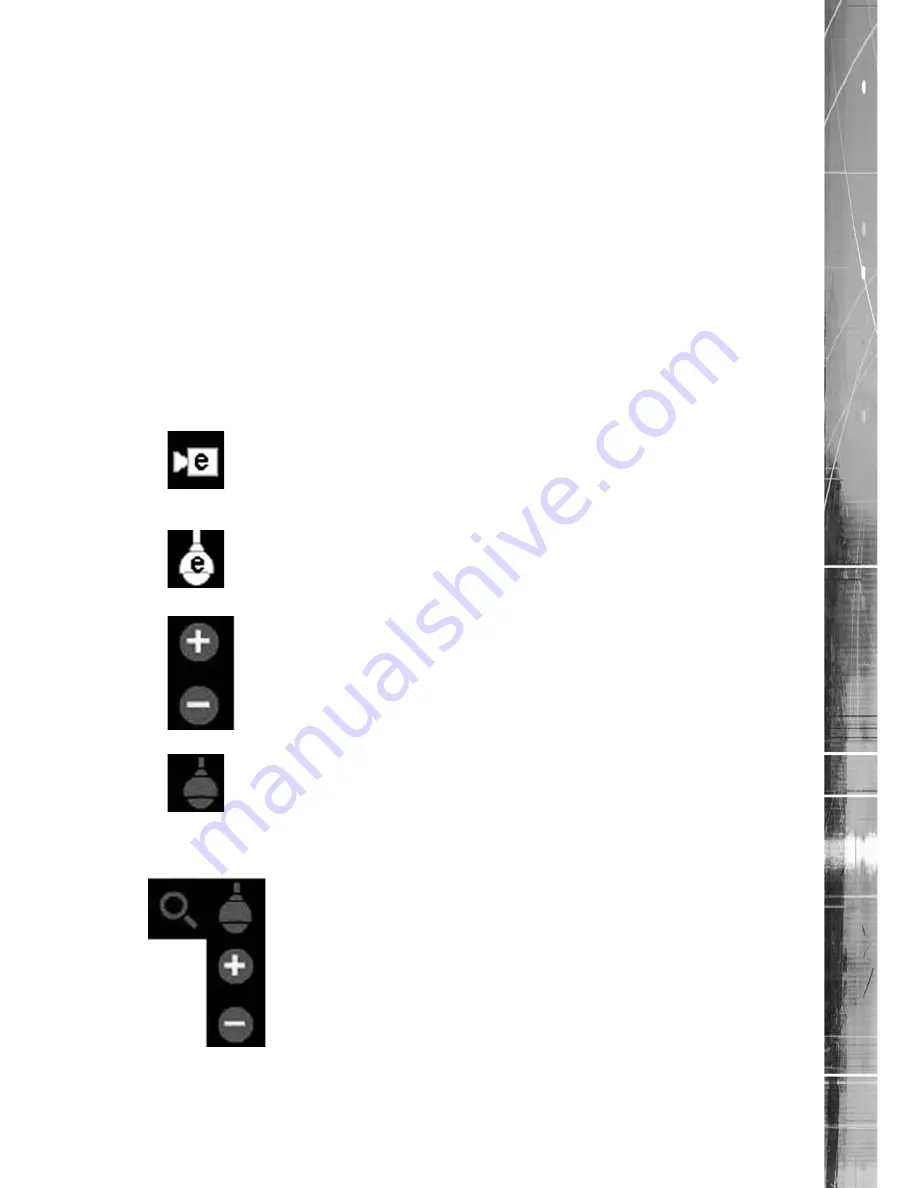
Symbol 

Mode/Camera Type   

Options Available


 Fixed Camera 

                                eZoom                Use this option to zoom into areas  of the image. The camera itself is 

not being directly controlled. Use the  mouse to select a point on the  

image. Use the + and - symbols illustrated below to zoom in / out.


ePTZ mode 

Use this option to zoom into areas of the image. The camera itself is 

not being directly controlled. Use the cursor to select a point on the 

image. Use the + and - symbols illustrated below to zoom in / out. 


  Zoom IN / OUT 

When displayed, use these buttons to zoom in / out of the image.


PTZ Mode 

Use this option to directly control an Oracle dome camera via the 

Point&go feature. Rolling the mouse over the icon will display more 

Telemetry command options (detailed below).


 To cycle through these options, click on the currently displayed symbol 

i.e. click on the Zoom symbol to display the 


Iris option.


  PTZ Zoom 

 When displayed, use the  + and - symbols to utilise the camera’s Zoom 

function. 


Intelligent Security & Fire Ltd

Summary of Contents for DV-IP RT

Page 1: ...DV IP RT Installation and Operation Guide I n t e l l i g e n t S e c u r i t y F i r e L t d ...

Page 2: ...es 4 Important Safeguards 6 Installing the Unit 8 Configuring the Unit 22 Remote Control 24 Main Menu 26 Navigating The Configuration Menus 27 System Settings 30 Console Settings 43 Camera Settings 54 Record Settings 59 Alarm Settings 69 Network Settings 84 Analytics Text 98 Archive 103 Oracle Dome Configuration 104 Unit Operation 114 Appendix A 136 Appendix B 137 Appendix C 139 Appendix D 140 App...

Page 3: ...a colour coded Softkey interface with configuration menus common to both local monitor and web interface making for easy set up and operation Dedicated Micros trademark plug and play intuitive set up and user friendly interface helps keep installation and operator training to a minimum The DV IP RT includes as standard internal storage with expansion available via external high speed SATA ports A ...

Page 4: ...iter and USB ports for download of video archive to external flash memory and uploading software updates Optional external keyboard available Configuration via USB mouse and USB QWERTY keyboard BS8418 compliant The DV IP RT has NetVu Connected technology built in to ensure maximum compatibility with future developments in networked security NetVu Connected technology enables the DV IP RT to fully ...

Page 5: ... a Dedicated Micros Oracle Dome simply by clicking an area of the monitor The camera will instantly respond positioning the selected area in the middle of the screen ideal for tracking movement through a scene ePTZ Dedicated Micros ePTZ uses an advanced image interpolation algorithm that reveals detailed information that simple pixel stretching digital zoom commands cannot Users can operate ePTZ a...

Page 6: ...s a common occurrence Regulatory Notes and FCC and DOC Information USA and Canadian Models Only Warning This equipment has been tested and found to comply with the limits for a Class A digital device pursuant to part 15 of the FCC rules These limits are designed to provide reasonable protection against harmful interference when the equipment is operated in a commercial environment This equipment g...

Page 7: ...t supports an integrated CD DVD writer the following are additional warnings associated with installing and operating the CD DVD writer please pay particular attention to this information Caution Use of controls or adjustments or performance of procedures other than those specified herein may result in hazardous radiation exposure To prevent exposure to laser emanations harmful to the eyes do not ...

Page 8: ... please contact Dedicated Micros customer services in your region Choosing a location for installation The DV IP RT is designed to be desk shelf or rack mounted Ensure the DV IP RT is properly ventilated to protect from overheating Ensure there is a 3cm gap on both sides of the unit Ensure the receiving end of the IR remote control extender faces the operator position and is not more than 3 metres...

Page 9: ...it routes Various storage sizes are available dependant on the number of cameras the storage options and recording rate selected The picture quality can easily be increased if less than 30 days standard recording is required Note It is the Installer Owner s responsibility to ensure that the record duration is set to the necessary requirements of the application MultiMode Recording The unit support...

Page 10: ...lap LED s Power The Power LED will be green to indicate power is connected to the unit HDD Hard Disk Drive This will flash when images are being stored to the hard disk Network The Network LED will be green to indicate a connection Rear Panel connections 32 Input model 16 Input model 8 Input model RearPanelDwgServer eps I n t e l l i g e n t S e c u r i t y F i r e L t d ...

Page 11: ... RS 485 2 wire or RS232 5 wire SERIAL 4 PTZ RS 485 2 wire or RS232 5 wire USB 2x USB2 0 connectors IR Infra Red Input connector for IR Remote Control Extender NET1 RJ45 Ethernet network connector 10 100 Mb s Ethernet Network NET2 RJ45 Ethernet network connector 1 Gb s Ethernet Network KBD RJ12 connector for use with Dedicated Micros telemetry keyboards KBC1 KBC2 EXP RJ12 expansion port for future ...

Page 12: ...m row of connectors For consistency and quality of installation DM recommend one row is used for video inputs and the other for all required loop through connections onto other pieces of equipment e g monitors and matrices Note Remember the last piece of equipment in line must be terminated Double termination not removing termination from the unit will result in the 1V peak to peak video signal be...

Page 13: ...ckets AUDIO IN and AUDIO OUT The audio channel defaults to record camera 1 The following modes of operation are supported Challenge intruders from a Remote Video Response Centre RVRC Listen to local audio from a site at the RVRC Record local audio from a site to accompany video Replay all audio through a local Audio output not supported when Audio out is used as a challenge PA source Note The Audi...

Page 14: ...back Note Output 2 is currently only configurable via the NetVu ObserVer interface Step 5 Connecting to the Network The DV IP RT has both 10 100 1000Mbps labelled NET 1 and 10 100Mbps labelled NET 2 auto detecting network ports The Network port labelled NET 1 should be used for 1Gb Network Connections If utilising this port network configuration should be undertaken via the Configuration Menu page...

Page 15: ...ed for DHCP i e the unit is automatically allocated an IP address from a network DHCP server DHCP works by assigning an IP address at initial connection to the network It is possible however that this IP address can change without notification i e following power failure It is therefore recommended that the DV IP RT be allocated a fixed IP address A fixed IP address can be assigned via the Configu...

Page 16: ...camera specific inputs configurable as entry exit alarms The alarms support tamper proof detection using 1k in line and 5K end of line resistance The DV IP RT detects short circuit open circuit and contact closure This functionality is part of the advanced alarms supported on NetVu Connected products and includes features required for Central Monitoring It is compatible with the British Standard B...

Page 17: ... resistive value is 6 8K ohms 1K 5 6K Closed the resistive value is 1K ohms as the circuit does not see the 5 6K ohm resistor Open Circuit Tamper the resistive value is infinity as the circuit has been cut and therefore is open Short Circuit Tamper the resistive value is 0 ohms Step 8 Connecting Serial Ports Serial ports have two main uses 1 Connecting twisted pair telemetry for PTZ cameras 2 Prov...

Page 18: ...sed inconjunction with the unit should be set with RS485 unterminated at the Dome Pin connections for RS485 connection to a dome on serial port 3 4 are Dome Cable DV IP RT Serial Connector Yellow 1 TX Green 9 TX If the dome is being connected using an RS485 connection the dome address should be set to match the camera input number on the DV IP RT i e if the dome is connected to video input 3 the c...

Page 19: ...has three address switches refer to the Oracle Dome documentation for more information on hardware confguration UTC Red 1 Blue N R Yellow N R Serial Red 2 Blue Camera Number Yellow Camera Number Note To enable configuration of Oracle Dome menus an RS485 connection is required Step 11 Connecting IR Remote Control Extender Connect the IR Remote Control Extender to the IR Input socket This must be co...

Page 20: ...y unit Connect the mains lead to the unit and then to the wall socket or to a fused spur connection Check local regulations before installation Some countries require an Alarm Security device be connected to a fused spur and not a wall outlet socket I n t e l l i g e n t S e c u r i t y F i r e L t d ...

Page 21: ...tain an effective SATA link the length of all cabling from the unit to the connected device should not exceed two metres The unit s operating system will continue to utilise the internal hard disks if the external hard drive encounters a problem Dedicated Micros Managed Storage Expansion units A DM Managed Storage Expansion unit is connected via the SATA port A Managed Storage unit provides high c...

Page 22: ...ly advised that a fixed IP address be assigned a DHCP assigned address can change without notification i e following power failure If using the 1Gb network capability network connection via Network port Net 1 a fixed IP address can be assigned via the Network Settings 1Gb Network menu If connected via Network port Net 2 a fixed IP address can be assigned via the Network Settings Network menu For i...

Page 23: ...bpages The unit can be configured using the webpages To access these 1 Launch Internet Explorer or similar web browser package 2 Type the URL for the unit IP or DNS address 3 The Opening menu page will be displayed I n t e l l i g e n t S e c u r i t y F i r e L t d ...

Page 24: ...to DVR mode Note the DVR mode is the default mode of operation Toggle the speed of PTZ camera movement two speeds available Use the Zoom button to zoom in out with a selected camera Also used to zoom x2 into Live or Playback images This button will change the Zoom Keys operation to focus or iris functions when available Use this button to cycle through available cameras This button should be press...

Page 25: ... Softkeys Red Green Yellow Purple to directly access the corresponding function displayed on the menu screen The Number pad should be used to select specific cameras and preset positions when available Use the Playback buttons to interrogate recorded images Use the LIVE button to switch from Playback or menus to a LIVE display I n t e l l i g e n t S e c u r i t y F i r e L t d ...

Page 26: ...onic version of the DV IP RT Installation Operation Guide ObserVer Manual Select to open an electronic version of the NetVu ObserVer User Guide NetVu ObserVer is a free video management software package from Dedicated Micros that allows users to seamlessly view distributed images from any NetVu Connected product NetVu ObserVer Select to download the NetVu ObserVer video management software Java JR...

Page 27: ...ation menus the menu tree will be displayed The configuration pages are navigated using the menu tree displayed on the left of each page Selecting one of the menu options will display the relevant page Associated sub menus will then be available I n t e l l i g e n t S e c u r i t y F i r e L t d ...

Page 28: ...s to increase decrease by an increment of 1 use the Left Right Directional buttons to increase decrease by an increment of 10 Use the OK button to accept a new setting Use the coloured softkeys to select the accompanying colour option on screen i e red button to select the red option To undo changes made to any menu select the Refresh Purple option Entering Alpha Numeric Data via a Local Monitor N...

Page 29: ... clicking on it directly If viewing pages locally enter alpha numeric data via the Arrow Key Editor see above If viewing remotely enter via the PC keyboard If available click on the drop down menus to select settings Note A selected item in the drop down list will appear highlighted Navigating away from a page clicking on a different option on the menu tree will automatically save any changed sett...

Page 30: ...stem language to be set The language can also be changed for the current session only The Time and Date page allows the unit time and date settings to be adjusted including setting the timezone The Serial Ports page allows each of the four serial ports to be individually configured for one of a range of operations including EPOS debug PPP and telemetry The Audio page shows the settings available f...

Page 31: ...r of Cameras Shows the number of camera channels on the unit Global PPS Details the Global PPS Pictures Per Second recording rate for all cameras Video Storage Gbytes Highlights the available video storage capacity in Gigabytes Video Standard Displays the video standard adopted by the unit i e PAL NTSC MAC Address This is the MAC address assigned to the unit IP Address This is the IP address alloc...

Page 32: ... Framestore Revision This identifies the Framestore Revision the unit is running PC Apps Revision This identifies the revision archive of the Viewer amd associated PC Apps software Boot Software Rev Displays the infrastructure componentry software revision I n t e l l i g e n t S e c u r i t y F i r e L t d ...

Page 33: ...lled User Reset Export Log Blue Select this option to export log data to an inserted CD DVD or a connected USB device Total Codecs Details the current number of installed codecs Codecs Installed codecs currently operating as a codec will be highlighted light green Hover the cursor over individual buttons to display either On or Off On signifies that the codec is active as a codec Framestores Insta...

Page 34: ...nected will be highlighted light green Those not in use will appear dark green Failed Cameras Those camera channels where the connection is deemed to have failed will be highlighted light green Those working correctly will appear dark green I n t e l l i g e n t S e c u r i t y F i r e L t d ...

Page 35: ...atus of the unit s alarm contacts alarm zones and relay outputs Alarm Contacts Zones Relay Outputs Alarm Contacts Alarm Zones and Relay Outputs that are in an active state are shown light green In active ones appear dark green not illuminated I n t e l l i g e n t S e c u r i t y F i r e L t d ...

Page 36: ...d for the current session only System Language Select to change the system language setting Reset Red Select to reset the unit Note The unit MUST be reset to implement system language changes Session Language Select to change the language settings for the current session only Choose Select to immediately activate session language changes I n t e l l i g e n t S e c u r i t y F i r e L t d ...

Page 37: ...e Enter a current time for the unit Set Date Enter a current date for the unit Time Zone Select the relevant timezone offset from the accompanying drop down menu Note Time Zone changes will only take effect after a unit reset SNTP Server A Simple Network Time Protocol SNTP server allows external devices to connect and set their current date and time settings to that of the SNTP If required enter t...

Page 38: ...ort for Comms purposes EPOS Sets the serial port for connection to an EPOS Electronic Point Of Sale device Interface Type Choose the type of serial interface being used Select from RS232 RS485 or RS422 Baud Parity Data Stop Flow Control These options allow the Serial port communication settings to be configured Note When a telemetry protocol is selected these settings will default to pre determine...

Page 39: ...model Record Audio Challenge Select this option to record an audio challenge originating from an operator at an RVRC Audio Sample Rate Audio can be recorded at 8KHz 11KHz 16KHz or 22KHz Playback Sample Rate Audio can be played back at 8Hz 11KHz 16KHz or 22KHz Record AGC Select this option to activate the AGC function AGC helps produce a better quality recording by removing background noise distort...

Page 40: ...ting Select this option to activate the Email Reporting function refer to Network Settings E mail for more information Note When de selected here the Email Reporting menu will no longer be displayed in the menu tree Remote Reporting Select this option to activate the Remote Reporting function refer to Network Settings Remote Reporting for more information Note When de selected here the Remote Repo...

Page 41: ...pied added as required Note Use the 10 100Mbps network option Net 2 for SMB purposes the unique Server Name must be assigned via Network Settings Server Name Deinterlacemask Select this option to improve display clarity and minimise the comb effect that may be visible when recording high motion scenes in 4CIF mode Use Record Profiles For Tx Select this option when units required Video Tranmission ...

Page 42: ... Purple Select to save current unit settings to the selected media Restore Blue Select to restore previously saved settings from the selected media Note Selecting the Restore button will cause the system to reboot To From Select the relevant media device to save to or restore from i e USB or CD DVD Server Reset Red Select to cycle the power to the unit IMPORTANT To upgrade the unit insert a media ...

Page 43: ...ge can only be accessed if viewing the Configuration menus remotely via an IP connection The Viewer Defaults page allows the Viewer menu settings to be configured The Display page controls how the local monitors present information They control whether text will be displayed on the Main or Spot monitors the colour of that text and how long cameras being displayed in sequence will be shown on scree...

Page 44: ... the local cameras as shown below Server URL Server Name Camera Selection localhost local 1 4 1 8 or 1 16 System Select from 20 available systems using the drop down menu System Name If required enter a recognisable name for the system this name is held on the DV IP RT and represents the system Server URL Enter the IP addresses of the servers providing the video signals Server Name Enter a name fo...

Page 45: ...ra is allocated in each system i e to access Camera 1 in System 1 first select System 1 via the System Selection map then select Camera 1 Remote Cam Num Identifies the number the camera is allocated on its server Selecting this number via the Viewer menus will not result in images from that camera being displayed Server URL Identifies the URL address of the server the camera is located on Server N...

Page 46: ...Req Images displayed in multiscreen in the Viewer menus can be displayed in either High Medium or Low resolution Note These configurations can be changed on a NetVu Connected Server or DVR Default Multi Display This controls how the unit will display the multiscreen option when selected via the Viewer menus The default setting is 16 way Select from Full Quad 6 way 6 cameras displayed per monitor 7...

Page 47: ...llows cameras to be accessed and controlled via the Viewer menu In Decoder Mode connected cameras can be accessed viewed or controlled via Dedicated Micros Pick a Point system Note For further information regarding Dedicated Micros Pick a Point system please contact Dedicated Micros customer services in your region Applet Location The location of the unit s Viewer menu applet is displayed The defa...

Page 48: ...in the drop down list Sequence Dwell secs The sequence dwell time can be set from 1 to 99 seconds The dwell time is the period a camera s images are displayed before switching to the next camera in the sequence Spot monitor text It is possible to select text to be displayed on the spot monitor The text displayed will include time date camera number and camera title Spot Sequence Dwell The spot seq...

Page 49: ...ver holding the map The map image will be displayed if linking is successful The linked map can be in gif or jpeg format and should not exceed 500 by 350 pixels Map Screen Offset These co ordinates represent the top left corner of the map graphic as displayed in the Viewer menu Camera Select Select which camera is to be linked to the created hotspot Activate Hotspot Select to activate and display ...

Page 50: ...bsolute positioning However if the dead centre of the hotspot is selected the camera will be viewed from its current location The absolute positioning point will depend on the data entered here A setting of 0 would result in the camera facing its Original base position To change the preset position enter a number between 1 and 360 A setting of 20 would set the preset position to 20 degrees to the ...

Page 51: ...menu pages remotely i e via the webpages To save map data highlight and copy all text displayed in the Map Data text window then save this data as a text file To import data copy relevant text from an external location and paste into the Map Data text window When the menu is exited this data will be used as the Map Config settings Note If importing data remember to first save any current map data ...

Page 52: ...ill limit access to the unit via an FTP connection Video FTP Assigning username and password requirements for the Video FTP function will limit access to the Video FTP archiving feature used with DM s NetVu ObserVer Telnet Assigning username and password requirements for Telnet connections will limit Telnet access to the unit Telnet can be used to upgrade the unit Serial Assigning username and pas...

Page 53: ...igning Remote Users access privileges will limit access to the Viewer pages for remote users When implemented the remote user will be prompted for a username and password before access to the Viewer pages via the main menu will be granted Note There are no default usernames and passwords for any of the Account Types If none are assigned access will be granted to all users and no request for a user...

Page 54: ...guration of all connected local camera channels The I P Camera page allows configuration of incoming digital video streams originating from an IP address The Camera Setup page allows the colour and contrast settings for each individual camera to be adjusted with a dynamic preview available The Camera Telemetry page enables telemetry capable cameras to be configured I n t e l l i g e n t S e c u r ...

Page 55: ...ill default to Colour If Monochrome cameras are used select Mono Selecting Mono will remove colour patterning If a particular channel is not in use or the camera has failed select Not Connected Term The unit will automatically terminate the camera input with 75Ω This should be disabled if the video feed is looped through to another device Fail Rep Select this option to activate a Failure report in...

Page 56: ...ideo stream Title Displays the camera title Mode Select the type of IP camera i e if the stream is originating from a NetVu Connected server select NetVu Server If from a NetVu camera such as a Dedicated Micros CamVu 2000 select NetVu Camera URL Edit the URL address of the IP camera source Port If required edit the port input data This will default to 80 HTTP Chan If required edit the channel inpu...

Page 57: ...justment Copy to all Select this option to apply current settings to all connected cameras Camera Colour Select a colour value from 8 to 8 via the slidebar or enter a number directly into the accompanying textbox Camera Contrast Select a contrast value from 8 to 8 via the slidebar or enter a number directly into the accompanying textbox I n t e l l i g e n t S e c u r i t y F i r e L t d ...

Page 58: ...lemetry capable camera is connected the appropriate control protocol should be selected from the accompanying drop down list Refer to Appendix E for details of supported telemetry protocols Note All RS485 telemetry cameras should be untermimated at the camera dome for maximum performance capabilities Note The arrow button displayed next to each textbox allows settings to be replicated for those ca...

Page 59: ... customised to respond appropriately to the alarms and time of day A high degree of control and flexibility is possible using these options The IP Record page allows recording configurations to be created for a digital video stream originating from an IP address The Schedule page is used to configure the Timer Function this enables the unit to automatically be put into set unset mode at specific t...

Page 60: ...ble using the current configuration Timed Expiry If required all stored recorded video can be permanently deleted after a set number of days Set to 0 to de activate this function Camera Settings Choose the rate of non alarm recording to be used from the range of preset recording profiles The default settings are DV IP Real Time RT variant MPEG4 25pps JPEG 4pps Multimode DV IP Near Real Time NT var...

Page 61: ...he Advanced Profile Record menu Days Recording Displays the record duration possible using the current configuration Channel Enables selection of a specific camera for editing Copy To All Select to copy the current profile record settings to all camera channels Pre Trigger JPEG Enablng the Pre Trigger feature will buffer and store alarm recording prior to an event trigger in JPEG format It will us...

Page 62: ...further details Comp Select image compression format MPEG or JPEG PPS The accompanying dropdown list allows the number of frames captured per second to be set The pictures per second pps option allows either 6 5 2 1 0 5 0 25 or 0 1 pps to be recorded Pictures can also be recorded at Real Time speed 25pps 3 4 Real Time 18pps or 1 2 Real Time 12pps To disable record choose the No Record option Selec...

Page 63: ...ast forwards through recorded video it will access I frames only and skip P frames Having too long an interval can make viewing the images in these modes difficult to follow Note however that too short an interval will reduce the benefits of lower bit rate MPEG4 recording Channel Enables selection of a specific camera for editing Copy To All Select to copy the current profile record settings to al...

Page 64: ...Select image resolution format QCIF CIF 2CIF or 4CIF Rate_kbps If MPEG4 is selected the figure entered here will be the bit rate allocated A higher bit rate will provide better quality MPEG bit rates can be entered within the range of 45 2500K bits second Size If JPEG is selected the figure entered here will be the size of the JPEG transmitted in Kbytes JPEG file sizes can be configured within the...

Page 65: ...le Copy To All Select to copy the current record settings to all connected IP cameras Unset Set Override Normal This column shows the recording profile used by the camera when operating under Normal non Event conditions Comp Select image compression format MPEG or JPEG Res For both MPEG and JPEG recording select either High Medium or Low quality resolution settings Note To view a local IP camera l...

Page 66: ...e Mode Title text boxes Day Time Enter the time using the 24hr clock when Unset mode will begin Night TIme Enter the time using the 24hr clock when Set mode will begin Keyswitch A Keyswitch can be used to switch the recording profile Unset Set If required select Enable then choose a contact to be used in a specific zone as the Keyswitch Note When the Keyswitch option is set to Enabled It is necess...

Page 67: ...press the Add button The date will be added to the Holiday list To delete highlight and select Delete Weekends Select Enable to activate the Weekend function Set mode will now be active for the dates outlined below Start Select a Start day and time for Weekend mode End Select an End day and time for Weekend mode Note Weekend mode will remain activate each week until deselected I n t e l l i g e n ...

Page 68: ...End Date Enter an end date to protect video End Time Enter an end time to protect video Protect Length days Enter the number of days that selected files will be protected for Protect Select this option to protect recorded video for the selected time period s Unprotect Select this option to unprotect recorded video selected from the list Reload List This will refresh the video list according to the...

Page 69: ...m images from the associated primary camera will automatically be displayed in the Viewer menu The Activity Setup page allowed activation and configuration of the Activity feature on all video inputs The Activity feature enables cameras to automatically detect any movement changes within the video scene This can trigger a number of operations such as FTP alarm notification or an increase in the re...

Page 70: ...efault setting the alarm wil ltrigger when the input is opened Note If EOL alarms are to be used this option should not be selected i e leave set as Normally Closed EOL The End Of Line EOL option enables the inputs to detect any changes in the electronic input resistance A change outside the expected values will result in a Tamper Alarm short circuit or open circuit being detected and the system s...

Page 71: ...triggered more than the amount set in the nuisance counter it will remain de activated for another hour This will continue until the trigger value falls below the nuisance count setting To disable this feature leave the setting as 0 Stuck Time If any of the alarms detectors are active for a period longer than specified here they will automatically be omitted This time period is set in minutes Note...

Page 72: ...st exit the set zone If the user is still within the zone after this time period the alarm will be triggered Zone An alarm zone can be established to logically groups alarms and initiate actions when an alarm is activated there are 32 configurable zones Title This information is stored along with the relevant images in the database ensure this has relevance to the alarm zone Pre Alarm sec This is ...

Page 73: ...ime is active This is in compliance with BS8418 the British Standard for remote video reporting centres Diverting from the entry route during the countdown will result in the alarm being triggered immediately This allows staff entry without triggering an alarm prior to switching the system to Set mode Exit route Zone This creates deferred alarms along a specified route while the exit time is activ...

Page 74: ...s the facility to assign additional cameras to the zone These cameras will become part of the alarm sequence shown in the Viewer menus when the alarm zone is triggered Create Database Entry An alarm activation will be added to the database The zone title will be used as part of the entry information Alarm Relay Select to trigger an alarm relay folowing zone activation Select the specific relay via...

Page 75: ...on feature Refer to Activity Setup for more information Email Reporting The unit can send an email when an alarm is detected refer to Network E mail for more information Preset Camera The preset camera is the camera which will be sent to a designated preset position upon alarm activation Preset Enter the preset position number for the selected camera here refer to Unit Operation PTZ Program for mo...

Page 76: ...n menu Activity To Trigger Following Activity activation select Simple Response to trigger specific chosen responses from the options detailed below Select Zone to apply the Zone Input rules as configured in the Zone Input menu Refer to Zone Input for more information Note When Activity to Trigger is set to Zone the options detailed below are unavailable Copy To All Select to copy the current Acti...

Page 77: ...d cameras on the connected Spot Monitor Enable in Day This will enable Activity Detection when the unit is in Day Unset operation mode Enable in Night This will enable Activity Detection when the unit is in Night Set operation mode Enable in Weekend This will enable Activity Detection when the unit is in Weekend Override operation mode I n t e l l i g e n t S e c u r i t y F i r e L t d ...

Page 78: ...t in motion for Activity mode to function only when the camera is still Select Always Active for Activity mode to be in constant operation Activity Channel This is a drop down list of the video inputs on the unit selecting an input will display images from the corresponding video source Grid Editor Use the Grid Editor by placing cells in areas of the camera view where movement will trigger an alar...

Page 79: ... Set Select Clear to remove grids or select Set to add grids Activity Detection Select Enabled to activate the Activity Detection feature Activity Sensitivity This option allows the sensitivity setting to be established for the activity grid being configured There are five settings to choose from Indoor High Indoor Low Outdoor High Outdoor Low Very Low I n t e l l i g e n t S e c u r i t y F i r e...

Page 80: ...e displayed on the local monitor Select Jump To Primary Camera from the drop down list to activate this function Revert Display Mode after Alarm Enable this setting to make the unit return to the view displayed before the alarm activation Alarm Display Alert Enable this setting to display an alarm text alert in the colour specified in Alarm Colour in the Zone Actions Menu Alarm Relay 1 Select this...

Page 81: ...obal Relay Therefore the relay will close when there is notification on the system that any of the enabled video inputs has camera failure no 1V pk to pk signal System Set Relay 4 When selected the unit will automatically switch to Set mode following relay activation I n t e l l i g e n t S e c u r i t y F i r e L t d ...

Page 82: ...the video inputs on the unit selecting one of the inputs will display the corresponding video source Ensure this corresponds with the selected Channel Zone There are 16 VMD zones within the image that can be individually configured select the zone from the drop down list A selected zone can be re sized by clicking the mouse button use the USB mouse if viewing on a local monitor and then moving and...

Page 83: ...the VMD event to be triggered The default setting is 20 Pixel Change This setting is a percentage value of the overall change required in the grayscale to be included in the pixel count The percentage change is defined over the complete range of black to white a 100 pixel change would be from black to peak white The default setting is 20 VMD Ensure this checkbox remains selected Clear Cells Remove...

Page 84: ...connections to any viewing software or to another unit using this one as an IP source The Email page allows configuration of the Email feature The unit can automatically transmit an e mail to an SMTP Server following an event i e on receipt of an alarm or a camera failure notice The Remote Reporting page allows a Remote Video Receiving Centre s RVRC configuration details to be entered The RVRC wil...

Page 85: ...is the primary DNS server IP address for applications utilising domain names Max Transmission Rate This shows the maximum transmission speed for the network type being used Force 10BaseT operation The unit supports 10 or 100BaseT half duplex transmission Selecting this option will force the unit to operate at a 10BaseT connection Tx Image Buffers This is used in order to improve the picture delive...

Page 86: ...fore disconnecting the PPP Point to Point Protocol link if data has not been transmitted or received PPP Link Down Timer mins If for any reason the PPP connection is lost this is the time in minutes before the unit will be forced to drop the PPP connection I n t e l l i g e n t S e c u r i t y F i r e L t d ...

Page 87: ...an IP address subnet mask and default gateway will automatically be allocated from the network DHCP Server It is recommended that this be disabled as the DHCP address is automatically allocated from a pool of available IP addresses on power up If the unit loses power the connection could reset to a different number Setting the IP address disables DHCP Max Transmission Rate kbytes sec This shows th...

Page 88: ...Dedicated Micros 2009 88 DV IP RT I n t e l l i g e n t S e c u r i t y F i r e L t d ...

Page 89: ... resolution settings 4CIF 2CIF CIF or QCIF Size_rate For JPEG the figure entered will be the size of the JPEG transmitted in Kbytes For MPEG4 the figure will be the bit rate allocated A higher rate will provide better quality picture display JPEG file sizes can be configured in the range of 5 45Kbytes and MPEG bit rates in the range of 45 2500Kbits second ms This shows the number of pictures trans...

Page 90: ... data or in GOV Group of Video format RAW mode transmits a single I frame and then a sequence of P frames until a change in transmission is detected GOV mode sends I and P frames in a standard format i e I to P frame ratio as set by the record parameters I n t e l l i g e n t S e c u r i t y F i r e L t d ...

Page 91: ...SMTP Server that the e mail will be sent to The SMTP server will then forward this to the intended recipient Recipient Email This is the e mail address of the intended recipient Display Name Recipient This is the addressee name that will be shown in the email name field Reply to Email This field must be configured if the recipient is to reply to an e mail The unit does not accept incoming e mails ...

Page 92: ...email notification on activation of the Activity Detection feature Send Image Select to send accompanying image from supporting primary camera Log Email Select to log every e mail transaction that the unit issues Email Image Res Select resolution settings for images sent as thumbnail attachments Choose from Thumbnail LO low res MED medium res and HI high res I n t e l l i g e n t S e c u r i t y F...

Page 93: ... only one alarm receiving IP address you must enter the details in both the primary and secondary connection settings Secondary Dial Profile It is possible to select a separate dial profile for the secondary host Public NAT IP Address This is the public IP or domain name for a unit connected to the Internet via a NAT Router or Firewall This field should be left blank if NAT is not used e g a priva...

Page 94: ...e dormant the unit will Ping the ARC prior to sending reporting data Alarm Responder Port This specifies the network port number used for reporting to the alarm server In normal circumstances this should be left at the default value 23 Dial Retry Time secs If the initial connection attempt fails the unit will wait for the specified time period in seconds before attempting to re connect Dial Count ...

Page 95: ...tory will be located Image Directory This directory will be created when the initial image is uploaded to the webcam server it is the directory where all images will be saved on the server Image Filename Prefix This is an identifier for images sent from the unit and will be stored as a prefix to the file name Username If it is necessary to use an authentication process to access the webcam server ...

Page 96: ...e Always Enabled Enabled when system SET Enabled when system UNSET or Disabled Webcam Resolution Select a High Medium or Low webcam resolution settings to best match the monitor settings of the operator receiving the images I n t e l l i g e n t S e c u r i t y F i r e L t d ...

Page 97: ... download purposes FTP Control Port The default port for FTP use is port 21 If this port has already been allocated on the network it is possible to identify and allocate an alternative port Status Server Port Default The default port for the Server Status function is port 23 if this port has already been allocated on the network it is possible to identify and allocate an alternative port number F...

Page 98: ... If Scheduled has been selected in Download Options enter a time for the download to take place each day Poll time Minutes If Polled has been selected in Download Options enter the number of minutes which will elapse between the conclusion of one archive download and the start of the next Clear video protection after download This automatically clears the image protection from successfully downloa...

Page 99: ...e of Analytics based solutions The Text In Image page allows the unit to integrate text data with recorded images i e a cash register with a camera positioned at the point of sale The Keyword page can be used in conjunction with the Text in Image function Keywords can be entered which when detected will trigger an alarm Up to 30 keywords can be created The Archive page allows Event database inform...

Page 100: ...AnalyticsCapable DV IP RT The range of applications include Automatic Number Plate Recognisition ANPR Object Left and Removed Access Control People Counting and Perimeter Protection For further information regarding the range of Dedicated Micros Analytics solutions please call 44 0 845 600 9500 I n t e l l i g e n t S e c u r i t y F i r e L t d ...

Page 101: ...t are stored on the server and not how many are displayed on screen This allows more data to be saved than is shown Text Timeout This setting controls how long in seconds the text is shown onscreen selecting 0 will show the text indefinitely Channel Select the camera input for configuration from the drop down list This is the image source that the text will overlayed across Copy To All Select to c...

Page 102: ... establish how many lines of text will be visible on screen Background Colour A black background box appears by default around the text It is possible to change the colour of this box Select from the drop down list Text Colour The colour of the displayed text can be changed Select from the drop down list Enable Keywords This enables or disables the Keyword feature allowing the unit to treat certai...

Page 103: ...puts In turn this generates events in the event database The advantage of this feature is that it allows the user to see exactly which keyword triggered an alarm A total of 32 Keywords can be configured and each can be up to 20 characters in length All of the keywords will be active on the selected Zone keyword channel refer to Zone Input Input Note Increasing the number of keywords can significan...

Page 104: ...m to the archive It is recommended that this option be selected as it will ensure the downloaded video images can always be successfully viewed Check Media button Selecting this option will display the space required in megabytes for the chosen event period to be fully downloaded The space currently available on the CD DVD or USB device is also shown Archive Space Required Space required for archi...

Page 105: ...be established and configured The Patrol feature uses established preset positions to automatically pan tilt and zoom the camera in the selected sequence The Privacy Masks page allows privacy masking to be established and configured The Privacy Mask feature can be used to blank out sensitive or private areas which appear in the cameras field of view The OSD Settings page allows the Oracle Dome OSD...

Page 106: ...onal life time of the camera to date Total Time Active Details the total time the unit has been active in motion Time Since Restart Details the time since the camera was last reset Current Temp Details the current temperature of the camera unit Max Temp Details the maximum temperature the camera unit has reached Min Temp Details the minimum temperature the camera unit has reached Fan 1 Status Deta...

Page 107: ...ew IN Blue Use the button to zoom the camera view OUT Navigation Buttons Use the four navigation buttons to position the camera view Save Grey Select to save the entered preset title to the unit and the Oracle Dome camera memory Store Preset Red Select this button to store the current preset position to the Oracle Dome camera s memory Goto Preset Green Select this button to immediately send the ca...

Page 108: ...dentifying the current camera position Camera ID Selected camera channel Camera Title This is the title assigned to the selected camera channel Sector Select from sector 1 32 Sector Name Enter a name for the selected sector up to a maximum of 25 characters Red Use the button to zoom the camera view IN Blue Use the button to zoom the camera view OUT Navigation Buttons Use the four navigation button...

Page 109: ...able name for the Patrol 1 32 Up to 32 individual positioning manoeuvres can be added to a Patrol Note Selecting one of the 1 32 buttons will send the camera to that Preset position Preset Select a pre established Preset Speed Select the Speed the Patrol will progress to the next Preset position the speed can be set as a percentage of maximum capability Dwell Select the Dwell time in seconds the P...

Page 110: ...It is recommended that the camera be navigated to the exact centre of the area requiring the privacy mask before pressing the Start New button Red Use the button to zoom the camera view IN Blue Use the button to zoom the camera view OUT Navigation Buttons Use the four navigation buttons to position the camera view Note When Start New has been selected the and Navigation buttons can be used to set ...

Page 111: ...ect desired position to locate the Alarm Name Position information For all above functions the available positions are Top Left Top Right Bottom Left Bottom Right and Off No information displayed All options are then split into three further sections 1 2 and 3 This relates to the display line i e Top Left 1 would be the very top line Top Left 2 would be the line below etc This enables information ...

Page 112: ...e camera to best focus on its current view Select to activate Auto Flip When the Oracle Domes Auto Flip feature is activated it will rotate a camera 180 degrees when it reaches its maximum upper or lower extremity i e pointing directly upwards or downwards This enables a camera to continue a tilt manoeuvre i e if tilting in an upwards direction when the camera is pointing directly up it will rotat...

Page 113: ...amera to compensate for different lighting scenarios which can effect the colour quality of the displayed image Select Auto for the camera to auto compensate for white balance depending on current view Select Indoor to permanently set for best results in an indoor setting Select Outdoor to permanently set for best results in an outdoor setting Exposure The Oracle Domes Exposure setting can be set ...

Page 114: ...y Closed NO Normally Open or Disabled Action Select a preset position or a patrol action for the camera upon alarm event Relay Select an action for the relay Select Momentary for the relay to momentarily switch state Select Duration to switch relay status for the duration of the alarm Home Grey Select to send the camera to its predetermined home position Action Select a preset or patrol from the a...

Page 115: ...rator and installer use The coloured keys on the IR Remote Control correspond to the menu options displayed on screen Note The screen images shown throughout this section are those displayed on a local monitor If viewing remotely via the webpages the menu layout will differ slightly The function of the keys will change according to whether the unit is in Live or Playback mode Overleaf are describe...

Page 116: ...e currently selected camera in the top left segment followed by the next eight cameras and will increment all cameras by one if pressed again i e if cam 1 is shown top left cam 2 adjacent etc then the views will increment to cam 2 top left cam 3 adjacent etc Note For optimal performance it is recommended that the multiscreen view be matched to the number of connected cameras i e if four cameras ar...

Page 117: ...l Freezes current video display Green Rewinds current video Yellow Plays from current position Blue Fast forwards video up to current recording position Purple Next Opens the next page of the Viewer menu I n t e l l i g e n t S e c u r i t y F i r e L t d ...

Page 118: ...ocal monitor only Red Preset If Preset positions have been established for the PTZ camera select the Preset option followed by the relevant numeric button or via the number box displayed on screen Refer to the PTZ Profile menu for further details on establishing preset positions Note Presets will not work in ePTZ mode Green PTZ ePTZ Switches between PTZ and ePTZ mode In ePTZ mode it is possible to...

Page 119: ...he symbols shown below will only be displayed if viewing via a local monitor and not the webpages Symbol Mode Camera Type Options Available Fixed Camera eZoom Use this option to zoom into areas of the image The camera itself is not being directly controlled Use the mouse to select a point on the image Use the and symbols illustrated below to zoom in out ePTZ mode Use this option to zoom into areas...

Page 120: ...he camera if applicable for the selected camera Aux Wipe Select this option to send the Wipe command to the camera if applicable for the selected camera Aux Lights Select this option to send the Lights command to the camera if applicable for the selected camera Aux Keypad Select this option to send additional Auxilliary commands to the camera i e if the selected camera has an Auto Pan function ass...

Page 121: ...t the camera then press Next Preset preset number Note When entering a new preset any previous preset assigned to that number for the same camera will be overwritten Yellow Select This option will send the camera to the stored Preset1 position Blue Set Origin The Origin option allows a base position to be established for the Oracle dome camera The camera will register this position as zero degrees...

Page 122: ...d across the screen Green Select This option enables sub menu content selection dependent on the protocol selected Please refer to the specific camera documentation for further guidance Yellow Return This option enabes sub menus to be exited dependent on the protocol selected Please refer to the specific camera documentation for further guidance Blue Menu Exit This option will fully exit any embed...

Page 123: ...rrespondingly numbered camera The default numeric selector map can be replaced by a gif jpeg image The image can include hotspots which link to available cameras Cameras are then selected via the hotspots Refer to Console Map Config for further details on creating Camera Maps Note For information on creating Camera Selection maps refer to the Console Map Config section for further information I n ...

Page 124: ...Timeline menu Yellow Event Displays the Events menu Blue Setup Opens the Configuration menu pages IMPORTANT Select this option to exit the Viewer menus This will be logged in the User Activity Log as the current user terminating the session Refer to Appendix C for further information regarding the User Activity Log Purple Back Returns to the previous page of the Viewer menu I n t e l l i g e n t S...

Page 125: ...e Selecting the Hour button Green will progress the video to a point exactly one hour prior to the time shown in the date time display Selecting the Hour button Yellow will progress the video to a point exactly one hour in advance of the ime shown in the date time display Selecting the 4Hrs Blue button will change the softkey options to four hour segments i e the user can progress four hours from ...

Page 126: ...e bottom left corner of the playback image Timeline The timeline allows navigation from the time and date currently shown in the Date Time Display window The scale changes to correspond to the time period chosen for investigation i e if a scale of one hour is selected it will be possible to move up to one hour prior or one hour in advance of the displayed time unless that selected time has not bee...

Page 127: ... increase it to four hours selecting it again will increase it to one day etc Left Navigation Arrow Green Selecting the left navigation arrow will play recorded images from the maximum prior time available via the current timeline i e if a one hour time scale is displayed selecting the Left Navigation Arrow will play video from one hour prior This can also be selected via the Green softkey button ...

Page 128: ...ellow softkey button to display the previous event or the Blue softkey button to display the next event To display the list of all available events highlight and select the current event The screen displays the date and time for the event shown in the dialog box A maximum of twenty events can be stored from connected devices Use the Yellow and Green navigation buttons to move through the saved eve...

Page 129: ...isplayed see above detailing the start date and time of the archive Select Mark again to establish an end time for the archive A maximum of eight copy periods can be added to the Copy Event List Green Clear In Playback mode select Clear to remove the last start or end mark added to the Copy Event List Yellow Archive Opens the Copy Menu Blue Seq On Off Select Seq On to display images from all conne...

Page 130: ...16 To add a chosen event to the download tick the Select checkbox Archive Media Select the media device USB or CD DVD for archive purposes Include Viewer Application Select whether the application required to view archived data is included in the download Used Blue Displays the space as a percentage already used on the chosen media device Required Green Displays the space as a percentage required ...

Page 131: ... USB export progress is displayed as a On completion the status will read Archive Complete To Copy Events Images to a CD DVD 1 Insert a CD DVD Device into the CD DVD drive on the front of the unit 2 Select CD DVD from the Archive Media checkbox 3 Select the Copy option Red to start archive 4 Selected items are then saved to the CD DVD 5 The CD DVD export status is displayed as a On completion the ...

Page 132: ... the coloured Softkeys at any time will display the coloured keys first and then access the equivalent coloured option displayed in the menus For a description of the button commands available on the IR Remote Control refer to the IR Remote Control section Using the optional Keyboards DM KBC1 DM KBC2 The unit can also be controlled using an optional Dedicated Micros keyboard This is connected via ...

Page 133: ...f no Softkeys are on screen For future use For future use Displays the Softkey options for the Audio functions for future use Forces all the cameras to record in alarm mode for three minutes or until the button is pressed again for future use Play mode Marks start and end of archiving point Live mode Opens the Archive Copy menu Live mode No functionality Play mode Starts fast forwarding from play ...

Page 134: ...ses video in playback Live mode puts the unit into playback using the last stored playback time Displays the Events list menu Opens the GOTO menu For future use Toggles control from Main to Spot monitor Allows the numeric selection of a camera numeric selection defaults to camera selection Allows entry of camera and Preset and numbers For future use For future use Triggers the wash function on a t...

Page 135: ...elemetry camera and also provides electronic zoom out Zooms out on a telemetry camera and also provides electronic zoom in Sends a Patrol command to a telemetry camera Instructs the selected telemetry camera to automatically pan on cameras that support this function Used as menu and on screen navigation keys Pan and tilt control for telemetry cameras In Play mode Used to Mark Start End positions l...

Page 136: ...as Cameras can be selected either by using the numeric number buttons on the keypad or via the Up Down camera CH key on the IR Remote Control For numeric entries that require two digit entry ensure both digits are entered within the one second time out Electronic Zoom If the DVR is in Live or Playback mode pressing the Zoom IN button will Zoom x2 into the image Once zoomed in it is possible to nav...

Page 137: ... Description 1 RS485 A 9 RS485 B 5 Shield GND RS232 Connectivity Serial 1 2 Pin Description Desc 1 Data Carrier Detect DCD 2 Receive Data RX 3 Transmit Data TX 4 Data Terminal Ready DTR 5 Ground GND 6 Data Set Ready DSR 7 Ready to Send RTS 8 Clear to Send CTS 9 Ring Indicate RI RS232 Connectivity Serial 3 4 Pin Description Desc 2 Receive Data RX 3 Transmit Data TX 5 Ground GND 7 Ready to Send RTS ...

Page 138: ...2527 2541 2545 2564 2605 2609 2614 2618 2622 2631 2633 2636 Amstrad 2002 2009 2010 2012 2024 2045 2492 2498 2515 2515 2515 2521 2540 2605 26 09 2610 2618 2621 2633 Baird 2068 2081 2504 2517 2518 2618 Bang Olufsen 2000 Bauer 2617 Beko 2007 2027 2052 2180 2191 2228 2242 2269 2498 2588 2589 2616 2637 Binatone 2003 Blaukpunkt 2008 2079 2519 2625 2636 Brandt 2029 2033 2034 2075 2076 2081 2117 2174 2272...

Page 139: ...93 2494 2497 2508 2569 2571 587 602 603 607 639 Technics 2043 Toshiba 2015 2021 2051 2069 2090 2103 2137 2158 2159 2165 2179 2188 2194 2208 2211 2213 2217 2218 2222 2243 2244 2250 2271 2284 2288 2294 2303 2304 2313 2318 2319 2320 2321 2322 2328 2347 2350 2370 2375 2394 2409 24 21 2435 2437 2440 2465 466 467 485 487 489 490 496 497 503 508 526 574 54 591 595 606 607 632 642 AUTO SEARCH FOR A CODE T...

Page 140: ...lated video files are kept One log file will be created daily as a text file and will be named automatically using the date of creation and stored in the logs directory on the unit This can then be downloaded via ftp if required Action Stored Data User Login Username Local or Remote Login Local Archive Username Local or Remote control Media Remote Raw Archive 1 http Username Submission requesting ...

Page 141: ...l port connections on the rear of the unit 2 On the PC click Start Programs Accessories Communications Hyperterminal and create a new connection via the COM port using these settings Bits per second 115200 Data Bits 8 Parity None Stop bits 1 Flow Control None 3 Power the unit the Power LED on the unit will illuminate 4 Hyperterminal will display the communications information as the unit boots up ...

Page 142: ...mper proof alarm inputs via back panel Keyswitch input to select set unset 4 relay outputs AUDIO The user has the option to record and play back audio through the unit in real time Recorded with images audio can be played back directly from the unit via powered external speakers Audio output for on site PA Challenge Connections 8 16 dependant on model 1V pk pk RCA phono channels for lip synched Au...

Page 143: ...ternet browser I R Remote CONTROL Offering full system control Optional keyboards Supports Dedicated Micros keyboards DMKBC1 DMKBC2 NetVu Console TELEMETRY Built in RS485 Twisted pair protocols provide direct control of the numerous domes including but not limited to the following Coax BBV BBV RX100 Pelco Spectra Serial Dedicated Micros Oracle Dome AD Matrix AD 168 Matrix BBV RE485 StarCard Bosch ...

Page 144: ...Dedicated Micros 2009 144 DV IP RT Notes I n t e l l i g e n t S e c u r i t y F i r e L t d ...

Page 145: ...lpha Numeric Data via a Local Monitor 28 ePTZ 5 Event Page 127 Event Settings 113 Features 4 Features 40 Front Panel connections 10 FTP Download 96 Gb Network 87 Global Actions 80 Holiday Weekend 67 How to Program The IR Remote Control 137 Important Safeguards 6 Installation 10 Installation and 1 Installing the DV IP RT 12 Installing the Unit 8 Introduction 3 IP Camera 56 IP Record 65 Keyword 102 ...

Page 146: ...to a CD DVD 130 To Copy Events Images to a USB Device 130 To select cameras 135 Unit Operation 114 Unit Specification 141 Unit Status 33 User Accounts 52 User Activity Logging 139 Using a USB Mouse or the Webpages 29 Using Serial Ports 136 Using the IR Remote Control 28 Video 11 Video Control 116 VIDEO TIMELINE 5 Video Timeline 125 View Control 115 Viewer Defaults 46 VMD Activity Response Setup 76...

Page 147: ...Dedicated Micros 2009 147 DV IP RT I n t e l l i g e n t S e c u r i t y F i r e L t d ...

Page 148: ...cated Micros Slovenia Delavska cesta 26 4208 Sencure Slovenia Dedicated Micros Benelux Joseph Chantraineplantsoen 1 3070 Kortenberg Belgium Dedicated Micros Germany Hamtorstaße 9 41460 Neuss Germany Dedicated Micros Asia PTY 16 New Industrial Road 03 03 Hudson Techno Centre Singapore 536204 Dedicated Micros Middle East Building 12 Suite 302 P O Box 500291 Dubai Internet City Dubai United Arab Emir...

Reviews: