


SVR DU
AL
™
U
ser
’s M
anual
44
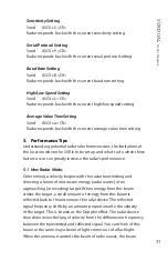
14. Appendix B - Cable Options
Various cable options exist for the SVR Dual™ .
14.1 S769-78613U-0
This cable allows the user to wire the unit to their preference . A
diagram and pin out appear below .
Figure 14.1
S769-78613U-0
Red = Power in
White = Ground
Brown = RS485- or Analog output-
Blue = RS232 RX input to radar
Pink = RS232 TX output from radar
Green = LVL sensor
Yellow = SDI-12
Grey = RS485+ or Analog
14.2 S769-78614-0
Cable has the same pin out as the S769-78613A-0 (Refer to section
3 .3) . In addition it has a black wire that connects to the negative and
red wire that connects to the positive of a 12 VDC supply .
Figure 14.2
Programming Cable


