


Each week :
●
Check the tyre pressures. On the side of each wheel cover, you’ll find the recommended tyre pressure.
A deflated tyre compromises the efficiency of the brakes and the fluidity of the wheelchair’s
movements.
●
Check the efficiency of the quick removal devices [paragraph 6.3], clean them, and if necessary, oil the
axles and dowels with a li le grease to ensure that the wheels can be simply removed and replaced.
Each quarter:
●
Check for wear on the front wheels, which may alter the rear seat of the wheelchair if significantly
worn. In this case, proceed with replacing the wheels [par. 6.2].
●
Check the bearings on the front and rear wheels, and on the fork rota on. In this case, replace the
bearings [par. 6.2].
●
Grease the mobile parts, such as the quick removal axles of the wheels and the guides for the wheels.
We recommend using silicon oil as a grease, as it's effec ve and non-staining.
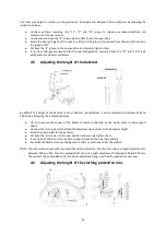
6.1 Replacing the tyre and air chamber
Disassembling the tyre and air chamber
●
Deflate the tyre
●
Install a special lever between the circle and the shoulder of the tyre, so that when the lever is lted,
the side of the wheel comes out (fig. 1 and 2)
●
Install another lever 100 mm from the previous point and repeat the opera on (fig. 3)
●
Slide the two levers around the whole circle to release the en re tyre.
●
Remove the air chamber, star ng with the side opposite the infla on valve (fig. 4)
●
Once the air chamber has been removed, you can easily remove the tyre to replace either or both of
them.
Assembling the air chambre and tyre
●
Remove the air chamber (deflated) in the tyre (fig. 5).
●
Insert the air chamber infla on valve into the whole intended for this purpose, located on the circle.
●
Around the whole circle, install the tyre, taking note of the direc on of the tyre, which indicates
whether it's the right or le drive wheel.
●
Install the opposite shoulder over the tyre, star ng from the point where the valve is, moving round in
both direc ons.
●
Insert the final part of the shoulder with the help of the levers intended for this, reversing the
instruc ons shown in Fig. 3, Fig. 2, and Fig. 1.
●
Inflate the tyre to the pressure indicated on its side.
FIG. 1
FIG. 2
FIG. 3
FIG. 4
FIG. 5
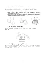
6.2 Replacing the castors and bearings
Wheel replacement (Fig. 6)
●
Unscrew and remove the “4” screws.
●
Remove axle “3” from its seat.
●
You can freely remove the wheel.
17


