background image


Data Device Corporation 


SB-3624XIX-3L0  Manual 

www.ddc-web.com


Rev D -10/15 

21 

DETAILED ARCHITECTURE 

5.1  Mechanical Outline 


Figure 12.   SB3624XIX-3L0 Mechanical Outline 

Artisan Technology Group - Quality Instrumentation ... Guaranteed | (888) 88-SOURCE | www.artisantg.com

Summary of Contents for SB-3624XIX-3L0 Series

Page 1: ...ess underutilized and idle equipment along with credit for buybacks and trade ins Custom engineering so your equipment works exactly as you specify Critical and expedited services Leasing Rentals Demos In stock Ready to ship TAR certified secure asset solutions Expert team I Trust guarantee I 100 satisfaction All trademarks brand names and brands appearing herein are the property of their respecti...

Page 2: ...obotics Gimbal Control Process Control Systems Reliable and easy to use DDC s half size PCI card provides intelligent interfacing between a Synchro or Resolver s output and a PCI Bus Custom Design Capability DDC can customize designs for all cards ranging from simple modifications of standard products to fully customized solutions for commercial military aerospace and industrial applications Artis...

Page 3: ...of these single chip and hybrid converters are based on ASIC designs yielding the most reliable converters ever offered and are the building blocks for DDC s card level products Military and industrial applications include radar IR and navigation systems fire control flight instrumentation simulators motor motion feedback controls and drives and robotics systems MIL PRF 38534 processing is availab...

Page 4: ...the latest information All rights reserved No part of this Manual may be reproduced or transmitted in any form or by any mean electronic mechanical photocopying recording or otherwise without the prior written permission of Data Device Corporation 105 Wilbur Place Bohemia New York 11716 2426 Tel 631 567 5600 Fax 631 567 7358 World Wide Web http www ddc web com For Technical Support 1 800 DDC 5757 ...

Page 5: ... 2010 69 Figure 34 Synchro or Resolver Direct Input Signal Configuration swap the two labels Synchro and Resolver Direct Also on Pg 69 Table 10 the Location for each Input Type changed to the following 2V Direct Lower Sockets 11 8V Resolver Lower Sockets 11 8V Synchro Upper Sockets 90V Synchro Upper Sockets D 10 2015 All New software package release compatable with Windows Vista Windows 7 and Wind...

Page 6: ...nal Input Configuration 12 4 2 3 Input and Output Options 13 4 3 Driver Installation 14 4 3 1 Windows Vista 7 8 Driver Installation 14 4 3 2 Windows 2000 XP Driver Installation 14 4 3 3 Windows NT Driver Installaltion 17 4 3 4 Linux Driver Installation 17 5 DETAILED ARCHITECTURE 21 5 1 Mechanical Outline 21 5 2 Synchro Resolver to Digital Channels 22 5 2 1 Signal Connections 22 5 2 2 Bandwidth 23 ...

Page 7: ... Read Angle Information 48 6 5 2 Set Oscillator Frequency 50 6 5 3 Set Amplitude 50 7 LIBRARY FUNCTION CALLS 51 char WINAPI Initialize int card 51 int WINAPI End_SelfTest int Card 52 int WINAPI Get_Card_Type int Card 53 int WINAPI Get_DLL_Version void 53 int WINAPI Get_Last_Error char ErrorMsg 54 int WINAPI Read_Bandwidth int Card int Channel 55 int WINAPI Read_Bite int card int channel 56 int WIN...

Page 8: ...API Program_Inhibit int Card int Channel int Control 71 void WINAPI Program_Resolution int Card int Channel int Resolution 72 void WINAPI Reset_Counter int Card int Channel 73 void WINAPI Twospeed_Inhibit int Card int Channels 74 WORD WINAPI Read_Angle_WORD int Card int Channel 75 WORD WINAPI Read_Converter int Card int Channel 76 8 ORDERING INFORMATION 78 Artisan Technology Group Quality Instrume...

Page 9: ... 19 Modfy Device Window 33 Figure 20 Modify Pull Down Menu 33 Figure 21 Device Number in Use Warning 33 Figure 22 Modify Device Window Close 34 Figure 23 Motion Feedback Devices Window Device Assigned 34 Figure 24 Motion Feedback Devices Window Show all Devices 34 Figure 25 Device Driver Information Window 35 Figure 26 Motion Feedback Devices Window Close 35 Figure 27 New GUI Workspace 36 Figure 2...

Page 10: ...e 4 Oscillator Type 13 Table 5 Input Type 14 Table 6 Dynamic Characteristics 23 Table 7 Velocity Characteristics 24 Table 8 BIT Fault Conditions 25 Table 9 Angular Position Screen 45 Table 10 Self Test Result Codes 48 Table 11 Register Format 48 Table 12 Oscillator Frequency 50 Table 13 Oscillator Amplitude 50 Table 14 ErrorMsg Values 54 Artisan Technology Group Quality Instrumentation Guaranteed ...

Page 11: ...ices You may not use the Product to permit any Device to use access display or run other executable software residing on the Workstation Computer nor may you permit any Device to use access display or run the Product or Product s user interface unless the Device has a separate license for the Product Storage Network Use You may also store or install a copy of the Product on a storage device such a...

Page 12: ...and all of its component parts EXPORT RESTRICTIONS You acknowledge that the Product is of U S origin and subject to U S export jurisdiction You agree to comply with all applicable international and national laws that apply to the Product including the U S Export Administration Regulations as well as end user end use and destination restrictions issued by U S and other governments LIMITED WARRANTY ...

Page 13: ...to time exercised subject to applicable law a return of the price paid if any for the Product or b repair or replacement of the Product that does not meet this Limited Warranty and that is returned to DDC You will receive the remedy elected by DDC without charge except that you are responsible for any expenses you may incur e g cost of shipping the Product to DDC This Limited Warranty is void if f...

Page 14: ...ERWISE UNDER OR IN CONNECTION WITH ANY PROVISION OF THIS SLA EVEN IN THE EVENT OF THE FAULT TORT INCLUDING NEGLIGENCE STRICT LIABILITY BREACH OF CONTRACT OR BREACH OF WARRANTY OF DDC OR ANY SUPPLIER AND EVEN IF DDC OR ANY SUPPLIER HAS BEEN ADVISED OF THE POSSIBILITY OF SUCH DAMAGES LIMITATION OF LIABILITY AND REMEDIES Notwithstanding any damages that you might incur for any reason whatsoever inclu...

Page 15: ... or written communications proposals and representations with respect to the Product or any other subject matter covered by this SLA To the extent the terms of any DDC policies or programs for support services conflict with the terms of this SLA the terms of this SLA shall control The Product is protected by copyright and other intellectual property laws and treaties DDC or its suppliers own the t...

Page 16: ...rical Static Discharge ESD physical shock or improper power surges and that precautions are taken to avoid electrocution Warnings Turn off power to the computer hardware and unplug from wall NEVER insert or remove card with power turned on Ensure that standard ESD precautions are followed As a minimum one hand should be grounded to the power supply in order to equalize the static potential Do not ...

Page 17: ... necessary to understand the operation of the chip set This manual provides detailed documentation on the functions of the library 2 6 Technical Support In the event that problems arise beyond the scope of this manual you can contact DDC by the following US Toll Free Technical Support 1 800 DDC 5757 ext 7771 Outside of the US Technical Support 1 631 567 5600 ext 7771 Fax 1 631 567 5758 to the atte...

Page 18: ...oftware has the capability to display position for either six channels of single speed or three channels of two speed Included with each SB 3624XIX 3L0 PCI Card is the Synchro API Library with example source code that allows users to easily write their own application software for the card 3 2 System Requirements The PC must be configured with a Windows 2000 XP Vista 7 8 or Linux 32 64 bit operati...

Page 19: ...ositioning and valve control This device is ideal for test engineers and developers to perform lab testing on these types of applications Applications include modern high performance industrial and military position feedback and control systems Typical motion feedback applications include motor control machine tool control antenna control robotics and process control systems The SB 3624XIX 3L0 is ...

Page 20: ... Synchro Vrms L L 2 direct 11 8 90 90 Zin line to line Ohms 10M 20pF 105k 195k 250k Zin each line to ground Ohms 70k 130k 125k Resolver Vrms L L 2 differential 11 8 90 Zin single ended Ohms 140k 70k 195k Zin differential Ohms 280k 140k 130k Common mode Range V max 8 30 180 REFERENCE INPUT Solid State Option P N Option 1 2 3 4 Option 5 6 7 8 Option 9 Carrier Frequency Hz 47 7k 47 7k 60 Type Differe...

Page 21: ...E POWER SUPPLY Voltage Vdc 5 5 Current 0 655A min with oscillator no load 1 725A max with oscillator loaded TEMPERATURE RANGE Operating C 0 to 71 Storage C 40 to 85 PHYSICAL CHARACTERISTICS Short half size PCI format in 6 875 x 4 2 x 0 57 Notes 1 Add 1 minute to specified accuracy for transformer isolated cards 2 in parallel with 3 Expect 1 LSB jitter for frequencies between 47 and 1 kHz Artisan T...

Page 22: ...gainst static damage Use a wrist strap if available or ensure proper static grounding by touching the power supply cover WITH POWER OFF Insert the card at a slight angle so that the connectors first protrude from the rear opening and then gently press the card into the motherboard connector Secure with proper hardware Make sure that adjacent cabling and wiring do not hinder the airflow around the ...

Page 23: ... L A T I O N Data Device Corporation SB 3624XIX 3L0 Manual www ddc web com Rev D 10 15 8 Figure 2 SB 3624XIX 3L0X PCI Card Block Diagram Artisan Technology Group Quality Instrumentation Guaranteed 888 88 SOURCE www artisantg com ...

Page 24: ...y way of configuration registers built into the card These registers are configured at the factory to contain the optimum values for the operation of the SB 3624XIX 3L0 The SB 3624XIX 3L0 PCI card and software drivers allow for shared interrupts thus simplifying the installation and reducing the risk of device conflicts Once the card has been properly installed its configuration information is sto...

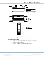
Page 25: ...dc web com Rev D 10 15 10 Figure 3 Mating Connector Suggested Mating Connector Solder Back Acon HBW 3268K 3207 includes hood and shell Ribbon 3M 10168 6000EC Card has 3M 68 pin connector N10268 5242 VC Artisan Technology Group Quality Instrumentation Guaranteed 888 88 SOURCE www artisantg com ...

Page 26: ...5 42 ZI ch 6 9 B ch 6 43 A ch 6 10 N C 44 A GND 6 11 S1 6 45 S3 6 12 S2 6 46 S4 6 13 RL 6 47 RH 6 14 N C 48 A GND 5 15 S1 5 49 S3 5 16 S2 5 50 S4 5 17 RL 5 51 RH 5 18 N C 52 A GND 4 19 S1 4 53 S3 4 20 S2 4 54 S4 4 21 RL 4 55 RH 4 22 N C 56 A GND 3 23 S1 3 57 S3 3 24 S2 3 58 S4 3 25 RL 3 59 RH 3 26 PWR GND 60 A GND 2 27 S1 2 61 S3 2 28 S2 2 62 S4 2 29 RL 2 63 RH 2 30 PWR GND 64 A GND 1 31 S1 1 65 S...

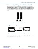
Page 27: ...an place the jumper block in either of the positions as shown in Figure 4 The board comes configured from the factory for velocity output Figure 4 J2 Jumper Configuration 4 2 2 Signal Input Configuration Figure 5 Synchro or Resolver Direct Input Signal Configuration The Synchro or Resolver Direct input options are configured by factory installation of thin film resistor networks within socket loca...

Page 28: ...ockets 11 8V Resolver DDC 49530 Lower Sockets 11 8V Synchro DDC 49530 Upper Sockets 90V Synchro DDC 49590 Upper Sockets Figure 6 Resolver Signal Input Configuration 4 2 3 Input and Output Options Table 4 Oscillator Type SB 3624XIX 3L0 X Vrms Range Frequency Range Voltage Type A 0 26 Vrms 360 7 KHz 1 5 VA Transformer Isolated B 0 115 Vrms 57 440 KHz 1 5 VA Transformer Isolated Artisan Technology Gr...

Page 29: ...er Installation 4 3 1 Windows Vista 7 8 Driver Installation The software package SB36040S0 must first be installed Installation of this package is easily completed by following the Installshield Wizard after opening the SB36040S0 exe file Once the software has been installed the hardware must be installed After successfully installing both the software and hardware the drivers will automatically b...

Page 30: ...b com Rev D 10 15 15 Figure 7 Add New Hardware Wizard Screen 3 Click on the Next button Figure 8 Search for New Driver Screen 4 Click on Search for the best driver for your device 5 Click on the Next button Artisan Technology Group Quality Instrumentation Guaranteed 888 88 SOURCE www artisantg com ...

Page 31: ...M drive 7 Select the CD ROM drive option to install from CD ROM or Select the Specify a location option and Browse DVD to locate the SB 3624XIX 3L0 folder 8 Click on the Next button to locate the SB 3624XIX 3L0 device driver Figure 10 Install Driver From Location Screen 9 Click on the Next button to install the device driver Artisan Technology Group Quality Instrumentation Guaranteed 888 88 SOURCE...

Page 32: ...Insert the DDC Product Catalog DVD into the DVD drive 3 The DVD will auto start 4 Select the SB3624XIX 3L0 card software to install 5 Follow any instructions that may appear on the screen The computer will need to be rebooted for the device driver to run 4 3 4 Linux Driver Installation Linux is a free Unix type operating system developed under the GNU General Public License The source code for Lin...

Page 33: ...utions This guide was prepared using Fedora 12 To complete the Linux setup the user should be familiar with basic Linux procedures and commands mounting compiling etc If you are unfamiliar with Linux try visiting some of these sites for helpful documentation www ora com www kernel org www linux org www linuxmall com www amazon com www ssc com www linuxhq com Documentation can also be found at any ...

Page 34: ...ip of all of the files to normal user and then exit superuser mode chown R users username exit The driver card manager and sample program will now be available in the selected working directory 4 3 4 2 Device Driver Upon installation the device driver binary for the SB 3624x card must be compiled and placed in the common DDC directory This can be done through the following steps 1 Go to the workin...

Page 35: ...n be done through the following steps 1 Go to the working directory cd synchro 2 Go to the sb3624x directory under the drivers directory cd drivers sb3624x 3 Become the super user su root su 4 Run the Makefile script Make Note The KVER declaration found at the top of the Makefile script will need to be modified to reference the base of the kernel source tree if it is not found at lib modules shell...

Page 36: ...624XIX 3L0 Manual www ddc web com Rev D 10 15 21 5 DETAILED ARCHITECTURE 5 1 Mechanical Outline Figure 12 SB3624XIX 3L0 Mechanical Outline Artisan Technology Group Quality Instrumentation Guaranteed 888 88 SOURCE www artisantg com ...

Page 37: ...Signal Connections Synchro Mode Connect S1 S2 S3 S1 X S2 Z S3 Y Resolver Mode Connect S3 SIN S1 SIN S2 COS S4 COS Single ended mode connections When using 2v single ended configurations S1 and S4 on card connector are no connect Use associated analog ground per output channel for S1 and S4 resolver outputs used Artisan Technology Group Quality Instrumentation Guaranteed 888 88 SOURCE www artisantg...

Page 38: ... 20 5 SCALE FACTOR Volts rps 125 5 2 8 0125 05 2 8 Not recommended Low bandwidths in low resolutions may induce spin around and the part will not settle High bandwidths in high resolutions may be used with carrier frequencies above 1 5 kHz 5 2 3 Synthesized Reference The synthesized reference eliminates errors due to phase shift within the synchro resolver sensor of up to 45 between the reference ...

Page 39: ...of rotation where a positive voltage is for increasing angle See Table 7 below for analog velocity characteristics Table 7 Velocity Characteristics PARAMETER UNITS TYPICAL MAX MIN POLARITY Voltage Range V 4 0 VOLTAGE SCALING resolution dependent RPS V Typical TR See Table 6 SCALE FACTOR Error Scale Factor TC Reversal Error Linearity Zero Offset Zero Offset TC Load PPM deg C output mV uV deg C k Oh...

Page 40: ...lly occurs when exceeding the maximum tracking rate or during power up 180 Phase Error 180 phase error input signal to reference input false null causes a BIT plus kickstarts the converter counter to correct the error 5 2 7 Two Speed Two speed allows resolutions greater than 16 bits to be achieved See CalculateTwoSpeed in Appendix A of the card manual for details Also refer to the RD RDC Applicati...

Page 41: ... Note If you did not receive the application software described on the following pages with your card please contact DDC customer service 6 1 Windows Software Overview 6 1 1 Motion Feedback Board Manager Application A Motion Feedback Board Manager Application contained in the Control Panel is used to define each Synchro Resolver card type in the system and the address for each Synchro Resolver car...

Page 42: ...user with example code on how to create a simple application using the API library 6 2 Linux Software Overview 6 2 1 DDC Card Manager Application The Card Manager provides the capability to assign logical device numbers to installed DDC devices for access from application programs built against the Synchro library To build and install the program type make on the command line in the drivers direct...

Page 43: ... for examples of how to build application programs 6 3 LabVIEW Support Software Overview 6 3 1 API Library function VI s The LabVIEW Support package includes VI s for every function call provided in the Synchro API Library for a user to develop a custom application in the LabVIEW environment 6 3 2 Example VI s A set of example VI s are included to demonstrate the usage of some of the library funct...

Page 44: ...eps below to install the software package for Windows from the downloadable ZIP file 1 Extract the zip file 2 Run the Setup exe file for the operating system version that applies to you x86 or x64 indicating 32 bit and 64 bit respectively 3 Follow the on screen instructions to complete the installation 6 5 DDC Card Manager Windows Vista 7 8 Once you have installed the hardware and software you are...

Page 45: ...e of the DDC Card Manager select Synchro Resolver Devices Confirm that the card is being read by the computer then assign a device number by selecting the appropriate card then using the drop down menu to select a corresponding device number Click Ok to finish device number assigning Artisan Technology Group Quality Instrumentation Guaranteed 888 88 SOURCE www artisantg com ...

Page 46: ...nstalled the hardware and software you are now ready to configure the card Device configuration is performed through the use of the DDC Card Manager Application 1 Turn on the computer 2 Click on Windows START 3 Click on SETTINGS 4 Click on CONTROL PANEL 5 Double click on the DDC MFB Manager icon circled in the screen image below Artisan Technology Group Quality Instrumentation Guaranteed 888 88 SO...

Page 47: ... to display status information for the installed card s Figure 18 Motion Feedback Devices Window Note The Device will default to none Each card must be assigned to a unique unused device number from 0 to 7 Card numbers cannot be shared 7 To assign the card to a new Device number select Modify to open up the Modify Device window Artisan Technology Group Quality Instrumentation Guaranteed 888 88 SOU...

Page 48: ...o 7 can be selected Note If a previously assigned device number is selected and the Prompt on Replace option is checked on the Motion Feedback Devices menu the following warning will appear Clicking on Yes will overwrite the previously assigned device number If the Prompt on Replace option was not selected a warning will not be displayed and the new device number will automatically overwrite the p...

Page 49: ... Motion Feedback Devices Window Device Assigned Note The Motion Feedback Devices window should display the device assigned to the selected device number 11 To show a log of all devices installed even if the card is not currently inserted select Show all devices from the Motion Feedback Devices window Figure 24 Motion Feedback Devices Window Show all Devices Artisan Technology Group Quality Instrum...

Page 50: ...es window The following Device Driver Information window will be displayed Figure 25 Device Driver Information Window 13 Select Close to close the Device Driver Information window and return to the Motion Feedback Devices window Figure 26 Motion Feedback Devices Window Close 14 Select Close to complete the card configuration and close the Motion Feedback Devices window The card is now ready for us...

Page 51: ...ce from the panel on the left hand side of the screen to create a new instance of a workspace Select the Synchro Resolver to Digital icon when prompted to select which Motion Feedback Profile to use Name the new workspace then click Next Figure 27 New GUI Workspace 2 All installed SB3624x devices that were assigned a device number and connected to the computer at the time of start up will appear S...

Page 52: ...ngs it is necessary that the system is not running or PAUSED To alter the parameters first click on the Edit paper with pencil icon located on the upper left hand side of the Properties window The parameters such as Oscillator Resolution Oscillator Settings Sampling Rate Speed Ratio Resolution and Bandwidth may be changed 1 Board Settings Note The sampling rate is only for aesthetics within the GU...

Page 53: ...ev D 10 15 38 Note The odd channel is fine and the even channel is coarse The ratio between the two grouped channels may be set to integer values between 1 1 128 1 Figure 29 One Speed Mode Figure 30 Two Speed Mode Artisan Technology Group Quality Instrumentation Guaranteed 888 88 SOURCE www artisantg com ...

Page 54: ...the Channels tab under the Settings label of the Properties window Each individual channel s settings may be set by dragging the slider to select the appropriate channel then selecting the desired settings from the drop down boxes The bandwidth may either be set to High or Low b The resolution may be 10 12 14 or 16 bits Figure 31 Channel Settings Artisan Technology Group Quality Instrumentation Gu...

Page 55: ...s in analog digital and binary formats Parameters are set and display options are selected using a combination of keyboard and mouse commands according to the chosen format 1 To access the Graphical User GUI Application Interface click on Start Programs Data Device Corporation SB3624x SB 3624x GUI Application as shown below Figure 32 Accessing the GUI Application Artisan Technology Group Quality I...

Page 56: ...nnel If the digital output is correct the Self Test results will indicate passed as shown below If a channel is not functioning the Self Test will return a failed indication Note If a channel fails Self Test the user can still use the Graphical Interface but the failed channel will not be accessible Figure 34 Self Test Results 4 To set the oscillator amplitude and frequency click Set Options this ...

Page 57: ...ion bandwidth and encoder emulation mode can be selected as shown in the menu below Channels can be selected individually or they can all be selected For two speed applications select the pair of channels along with the two speed ratio 6 Once the appropriate oscillator is selected the oscillator amplitude and frequency can be programmed by inputting the values into the Oscillator Settings windows ...

Page 58: ...vice Corporation SB 3624XIX 3L0 Manual www ddc web com Rev D 10 15 43 Figure 36 Options Screen Select Channel Shown Figure 37 Options Screen Resolution Shown Artisan Technology Group Quality Instrumentation Guaranteed 888 88 SOURCE www artisantg com ...

Page 59: ...set on the card For example if the resolution set on the card is 14 bits the A quad B resolution must be set to 14 bits or less not 16 bits 8 The Display Options section enables which type of display is shown in the main screen The binary display represents the digital angle Bit 1 180 Bit 2 90 Bit 3 45 etc The read delay defines the display update rate 9 Once the options are selected click on OK T...

Page 60: ...er signals have fallen below the specified voltage amplitude or there are no analog input signals connected to the R D converter Note Both SIN and COS signals of the R D converter must fall below 0 5 Vrms or else the BIT may only indicate a fault at certain angles 2 The synchro or resolver is moving at a rate greater than the R D converter can accommodate The dynamic capability of the R D converte...

Page 61: ... than 16 bit to be achieved For 2 Speed Theory review the following DDC documents The RD RDC applications manual system design section RD RDC manual and the Synchro Resolver Conversion Handbook Both of these documents can be downloaded from the DDC website at www ddc web com Note A quad B does not have any combining function when used in 2 speed mode Figure 40 Angular Position Screen Two Speed 6 5...

Page 62: ...all path The console application provides an easy method to evaluate angle position information and run self test 2 Enter the card number of the SB 3624XIX 3L0 card and hit Enter This will start the self test mode The self test results will indicate if the card is functioning properly Figure 41 Console Application Function Select Screen 3 The self test results will be displayed on the second line ...

Page 63: ...l channels on the card failed 0 x 0 All channels passed self test on power up Table 11 Register Format Ch 1 Ch 2 Ch 3 Ch 4 Ch 5 Ch 6 0 0 0 0 0 0 0 0 6 5 1 Read Angle Information 1 Type the code for the desired operation in the Enter Option field 1 to read Angles and hit Enter 2 The test results for the selected operation will be displayed in the console application screen Figure 42 Console Applica...

Page 64: ...to 6 Low low bandwidth and High high bandwidth Enter 2 to change bandwidth INHIBIT Monitors inhibit status for channels 1 to 6 Inh indicates data inhibited Track indicates data is tracking Enter 4 to inhibit a channel RESOLUTION Monitors resolution for channels 1 to 6 Enter 3 to change resolution Options 10 12 14 or 16 bits Encoder Mode Information Provides A quad B outputs 0 for On and 1 for Off ...

Page 65: ... 35 2023 0 Hz 6 5 3 Set Amplitude 1 Enter 9 to change Amplitude 2 To change the Oscillator amplitude enter the bit multiplier The bit multiplier which is an integer is determined by the following formula Amplitude bit multiplier X mV bit Table 13 Oscillator Amplitude Model Number Output Scaling mV bit Examples Bit Multiplier Resultant Amplitude Bit Multiplier Range IA 135 0 mVrms bit 26 0550 Vrms ...

Page 66: ... DESCRIPTION Opens and reads from the REGISTRY to get the card type Performs a string comparison with the card type to branch to the appropriate card specific routine Closes REGISTRY when finished Returns the card type from the given card number for error checking INPUT DATA Card an integer between 0 and 7 for the card of interest The card number is set in the Motion Feedback Board Manager RETURNE...

Page 67: ...ween 0 and 7 for the card of interest The card number is set in the Motion Feedback Board Manager RETURNED DATA This routine will return a 0x99 if the card was not initialized Otherwise the card will return a 1 if Self Test was successfully exited EXAMPLE CODE Code Result Returned Data int End End End_SelfTest 1 Exits Self Test for card 1 and returns a 1 if properly exited Self Test mode Artisan T...

Page 68: ... card installed and assigned to Card Valid Values PCI SB3620x PCI SB3621x PCI SB3622x PCI SB3624x EXAMPLE CODE Code Result Returned Data Get_Card_Type 0 Returns the card type of card 0 int WINAPI Get_DLL_Version void DESCRIPTION This routine returns the current version of the synchro dll Can be displayed in applications and helps to maintain version control INPUT DATA There is no input data for th...

Page 69: ...rror message RETURNED DATA ErrorMsg A int that represents the last error message Table 14 ErrorMsg Values Values Description 0 No Error 1 Could not open registry 2 Card Type is invalid 3 Card no initialized 4 Invalid direction 5 Could not open device 6 Cound not close device 7 Invalid channel 8 Invalid option 9 Invalid range 10 Missing parameters 11 Invalid error code EXAMPLE CODE Code Result Retu...

Page 70: ... for the card of interest The card number is set in the Motion Feedback Board Manager Channel an integer between 0 and 5 for the channel of interest RETURNED DATA This routine returns the Bandwidth as an integer 0 High 1 Low EXAMPLE CODE Code Result Returned Data int Bandwidth Bandwidth Read_Bandwidth 2 2 Reads the bandwidth as an integer of card 2 channel 2 Artisan Technology Group Quality Instru...

Page 71: ...ate a fault at certain angles The synchro or resolver is moving at a rate greater than the R D converter can accommodate The dynamic capability of the R D converter is determined by the bandwidth selection and the resolution refer to hardware setup The error exceeds approximately 100 LSB s This condition will occur during a large step and reset after the converter settles out INPUT DATA Card an in...

Page 72: ...een 0 and 7 for the card of interest The card number is set in the Motion Feedback Board Manager Channel an integer between 0 and 5 for the channel of interest RETURNED DATA This routine returns the turns count of a channel range 0x0000 to 0xFFFF EXAMPLE CODE Code Result Returned Data int Counter Counter Read_Counter 0 2 Returns the turns count of card 0 channel 2 Artisan Technology Group Quality ...

Page 73: ... card of interest The card number is set in the Motion Feedback Board Manager Channel an integer between 0 and 5 for the channel of interest RETURNED DATA This routine returns the direction of a channel as an integer 1 Up 0 Down EXAMPLE CODE Code Result Returned Data int Direction Direction Read_Direction 6 4 Returns the direction as an integer for card 6 channel 4 Artisan Technology Group Quality...

Page 74: ...of interest The card number is set in the Motion Feedback Board Manager Channel an integer between 0 and 5 for the channel of interest RETURNED DATA This routine returns the value of the Encoder for a given channel as an integer 0 On 1 Off EXAMPLE CODE Code Result Returned Data int Encoder Encoder Read_Encoder 5 3 Returns the encoder mode as an integer for card 5 channel 3 Artisan Technology Group...

Page 75: ... and 7 for the card of interest The card number is set in the Motion Feedback Board Manager Channel an integer between 0 and 5 for the channel of interest RETURNED DATA This routine returns the status of the inhibit bit for a given channel If the inhibit status is 9 then the card was not initialized EXAMPLE CODE Code Result Returned Data int Inhibit Inhibit Read_Inhibit 0 5 Returns the status of t...

Page 76: ...7 for the card of interest The card number is set in the Motion Feedback Board Manager Channel an integer between 0 and 5 for the channel of interest RETURNED DATA This routine returns an integer that represents the current resolution of a channel as either 10 12 14 or 16 bits If a 9 is returned than there was an error with the initialization of the card EXAMPLE CODE Code Result Returned Data int ...

Page 77: ...e card of interest The card number is set in Motion Feedback Board Manager RETURNED DATA This routine returns the Hex equivalent of the channels that fail as an integer The 0 bit is the most significant bit and the 6th bit is the least significant bit Register format Ch 0 Ch 1 Ch 2 Ch 3 Ch 4 Ch 5 0 0 0 0 0 0 0 0 0 x 99 is returned if the card did not initialize 0 x 20 Ch 0 fails 0 x 10 Ch 1 fails ...

Page 78: ...ing the entire test INPUT DATA Card an integer between 0 and 7 for the card of interest The card number is set in the Motion Feedback Board Manager RETURNED DATA This routine will return a 0x99 if the card did not initialize Otherwise the card will return a 1 if Self Test is started EXAMPLE CODE Code Result Returned Data int Start Start Start_SelfTest 1 Returns a 1 if in Self Test Artisan Technolo...

Page 79: ...d an integer between 0 and 7 for the card of interest The card number is set in the Motion Feedback Board Manager Channel an integer between 0 and 5 for the channel of interest RETURNED DATA This routine returns the angle of a given channel as a 32 bit long integer range 0x0000 to 0xFFFF EXAMPLE CODE Code Result Returned Data Read_Angle 3 5 Returns the angle as a 32 bit long integer for card 3 cha...

Page 80: ...s default values to card INPUT DATA Card an integer between 0 and 7 for the card of interest The card number is set in the Motion Feedback Board Manager RETURNED DATA This routine does not return any data EXAMPLE CODE Code Result Returned Data Close 7 Closes the device driver for card 7 Artisan Technology Group Quality Instrumentation Guaranteed 888 88 SOURCE www artisantg com ...

Page 81: ...ich is an integer is determined by the following formula Amplitude bit multiplier X mV bit Model Number Output Scaling mV bit Examples Bit Multiplier Resultant Amplitude Bit Multiplier Range IX 8 8 mVrms bit 1 0032 Vrms 114 X 0088 114 1 0032 Vrms 0 255 IA 135 0 mVrms bit 26 0550 Vrms 193 X 135 193 26 0550 Vrms 0 255 IB 635 0 mVrms bit 115 5700 Vrms 182 X 635 182 115 5700 Vrms 0 210 IC 17 6 mVrms b...

Page 82: ...n to the card INPUT DATA Card an integer between 0 and 7 for the card of interest The card number is set in the Motion Feedback Board Manager Channel an integer between 0 and 5 for the channel of interest Bandwidth an integer that is either a 0 or a 1 0 High and 1 Low RETURNED DATA This routine does not return any data EXAMPLE CODE Code Result Returned Data Program_Bandwidth 6 0 1 Sets the bandwid...

Page 83: ...the card INPUT DATA Card an integer between 0 and 7 for the card of interest The card number is set in the Motion Feedback Board Manager Channel an integer between 0 and 5 for the channel of interest Encoder an integer which is either a 0 turns Encoder On or a 1 turns Encoder Off RETURNED DATA This routine does not return any data EXAMPLE CODE Code Result Returned Data Program_Encoder 4 4 0 Turns ...

Page 84: ...dback Board Manager Channel an integer between 0 and 5 for the channel of interest Resolution 10 10 bit resolution 12 12 bit resolution 14 14 bit resolution 16 16 bit resolution Note Encoder A quad B resolution must be of equal or lesser value than the resolution set on the card For example if the resolution set on the card is 14 bits the A quad B resolution must be set to 14 bits or less not 16 b...

Page 85: ...change the Oscillator frequency enter the bit multiplier The bit multiplier which is an integer is determined by the following formula Frequency bit multiplier X Hz bit Board Type Output Scaling Hz bit Examples Bit Multiplier Resultant Frequency Bit Multiplier Range 60 Hz 7 6 Hz bit 60 8 Hz 8 X 7 6 8 60 8 Hz 8 255 402 8 Hz 53 X 7 6 53 402 8 Hz 400 Hz 57 8 Hz bit 404 6 Hz 7 X 57 8 7 404 6 Hz 6 255 ...

Page 86: ...outine Error checking is performed appropriate bits are masked and the new value is written to the card INPUT DATA Card an integer between 0 and 7 for the card of interest The card number is set in the Motion Feedback Board Manager Channel an integer between 0 and 5 for the channel of interest Control an integer that is either a 0 for inhibit or a 1 for uninhibit RETURNED DATA This routine does no...

Page 87: ... INPUT DATA Card an integer between 0 and 7 for the card of interest The card number is set in the Motion Feedback Board Manager Channel an integer between 0 and 5 for the channel of interest Resolution 10 10 bit resolution 12 12 bit resolution 14 14 bit resolution 16 16 bit resolution RETURNED DATA This routine does not return any data EXAMPLE CODE Code Result Returned Data Program_Resolution 0 0...

Page 88: ...rd an integer between 0 and 7 for the card of interest The card number is set in the Motion Feedback Board Manager Channel an integer between 0 and 5 for the channel of interest RETURNED DATA This routine does not return any data EXAMPLE CODE Code Result Returned Data Reset_Counter 0 2 Resets the turns count of card 0 channel 2 to zero Artisan Technology Group Quality Instrumentation Guaranteed 88...

Page 89: ... SB3624x_INHIBIT3 Ch4 0x40 SB3624x_INHIBIT4 Ch5 0x80 SB3624x_INHIBIT5 All channels SB3624x_INHIBITall INPUT DATA Card an integer between 0 and 7 for the card of interest The card number is set in the Motion Feedback Board Manager Channels an integer which represents the channels that will be inhibited RETURNED DATA This routine does not return any data EXAMPLE CODE Code Result Returned Data Twospe...

Page 90: ...outine INPUT DATA Card an integer between 0 and 7 for the card of interest The card number is set in the Motion Feedback Board Manager Channel an integer between 0 and 5 for the channel of interest RETURNED DATA This routine returns the angle of a given channel as a WORD range 0x0000 to 0xFFFF EXAMPLE CODE Code Result Returned Data WORD Angle Angle Read_Angle_WORD 3 5 Returns the angle as a WORD f...

Page 91: ... 1 track data INPUT DATA Card an integer between 0 and 7 for the card of interest The card number is set in the Motion Feedback Board Manager Channel an integer between 0 and 5 for the channel of interest RETURNED DATA This routine will return the digital data from the channel of interest in the form of a WORD range 0x0000 to 0xFFFF EXAMPLE CODE Code Result Returned Data WORD Converter Converter R...

Page 92: ...Data Device Corporation SB 3624XIX 3L0 Manual www ddc web com Rev D 10 15 77 Artisan Technology Group Quality Instrumentation Guaranteed 888 88 SOURCE www artisantg com ...

Page 93: ...former Isolated note 4 60 Hz 15 Hz 45 Hz B Notes 1 See TABLE 1 for accuracy vs frequency 2 Solid state input types use surface mount resistors and the reference input has a voltage divider network This voltage divider will allow for reference input ranges of 2 0 Vrms to 40 Vrms for the 26 Vrms nominal option or 50 Vrms to 130 Vrms for the 115 Vrms nominal option This is preset at the factory as sp...

Page 94: ...anual Windows GUI DLL s Libraries Software Provided CD Format 1 Mating Connector Slot Guide Hardware PCI Retainer and Screws STANDARD DDC PROCESSING FOR DISCRETE MODULES PC BOARD ASSEMLIES TEST METHOD S CONDITION S INSPECTION WORKMANSHIP IPC A 610 Class 3 ELECTRICAL TEST DDC ATP Artisan Technology Group Quality Instrumentation Guaranteed 888 88 SOURCE www artisantg com ...

Page 95: ...esolver line is supported by software designed to meet today s COTS MOTS needs The Synchro Resolver line has been field proven for military and industrial applications including radar IR and navigation systems fire control flight instrumentation simulators motor motion feedback controls and drivers and robotic systems As the world s largest supplier of Solid State Power Controllers SSPCs and Remot...

Page 96: ...ome Bunkyo ku Tokyo 112 0004 Japan Tel 81 3 3814 7688 Fax 81 3 3814 7689 Web site www ddcjapan co jp Asia Data Device Corporation RO Registered in Singapore Blk 327 Hougang Ave 5 05 164 Singapore 530327 Tel 65 6489 4801 Inside the U S Call Toll Free 1 800 DDC 5757 Headquarters and Main Plant 105 Wilbur Place Bohemia NY 11716 2426 Tel 631 567 5600 Fax 631 567 7358 Toll Free Customer Service 1 800 D...

Page 97: ...quipment Have surplus equipment taking up shelf space We ll give it a new home Learn more Visit us at artisantg com for more info on price quotes drivers technical specifications manuals and documentation Artisan Scientific Corporation dba Artisan Technology Group is not an affiliate representative or authorized distributor for any manufacturer listed herein We re here to make your life easier How...

Reviews: