
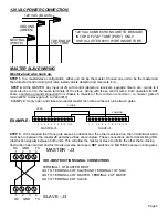
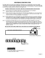
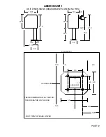

120 VAC POWER CONNECTION
120 VAC (BLACK)
NEUTRAL
GROUND
(GREEN)
4"x4" TUBE
(WHITE)
TOP END OF
120 VAC CONNECTIONS ARE TO BE MADE
IN TOP OF 4"x4" TUBE (POST). ONLY
USE UL-LISTED 600 V WIRE INSIDE TUBE.
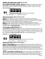
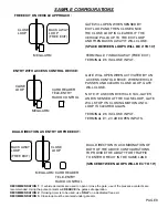
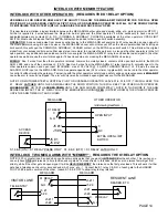
MASTER SLAVE WIRING
Master-slave wire hook up.
STEP 1
- In a master/slave configuration, either unit can be the master. Choose one unit to be the master and
then direct all control wiring to it (also install vehicle detector and receivers in it).
STEP 2
- At the MASTER, any input (at J5) with control (detectors, receivers, keypads, timers, etc...) wires to it
must also be run to the same terminals of the slave. Along with these control wires, both operators MUST
share a common ground connection from chassis to chassis (or from common to common , i.e. master gate J5
terminal #12 to slave gate J5 terminal #12)
EXAMPLE: If only open and close are used at master then three wires will run between gates.
1 2 3 4 5 6 7 8 9 10 11 12
1 2 3 4 5 6 7 8 9 10 11 12
MASTER- J5 SLAVE-J5
OPEN
CLOSE
COMMON
EXAMPLE:
STEP 3
- If it is required that if one gate senses an obstruction, the other reverses also, then 3 additional wires
must be run between the master
J3
and slave
J3
as shown below. These connections are for transmitting IRD
(obstruction signals) between both units. This will allow the master or slave to inform the other that a closing
obstruction has occurred and for it to also reverse and open.
SET
switches on
S2, 1-8
the same on both gates
MASTER - J3
SLAVE - J3
1 2 3 4
1 2 3 4
RX GND TX
RX GND TX
TERMINAL 1 OF MASTER MUST
GO TO TERMINAL 4 OF SLAVE AND TERMINAL 1 OF SLAV
GO TO TERMINAL 4 OF MASTER. TERMINAL 2 OF MASTE
GO TO TERMINAL 2 OF SLAVE.
IRD - OBSTRUCTION SIGNAL CONNECTIONS
Page 4