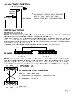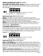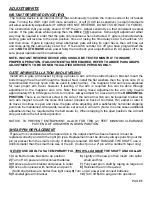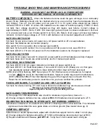
NOTE 1: MAXIMUM AMBIENT TEMPERATURE FOR INSTALLATION, 104 F.
NOTE 2: FOR AUTOMOTIVE USE ONLY, NO MOTORCYCLES, BICYCLES OR PEDESTRIANS.
NOTE 3: HEATER OPTION MUST BE USED IF TEMP IS (15F) OR BELOW TEMPERATURES.
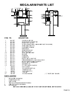
CONDUITS
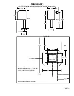
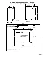
Conduits should be restricted to fit the 3.5"x3.5" opening in pedestal base. Location on pad should be
centered and spaced approximately 6" from edge of pad on drive way side ( in order to get the most reach out
of arm ). Conduits to be included should be 120 VAC main power, low voltage control wiring and one or two
extra for loop sensor leads. Conduit size should be limited to .5" when possible to reduce crowding if more
than four are needed. All conduits must be U.L. approved.
WIRING AND HOOKUP
(Only by a qualified electrician/installer!)
120 VAC
Be sure your main power (120vac) is OFF before attempting hookup. The 120 volts AC supply should be
terminated to the wires in top of the 4"x4" tube at the top of the chassis. Connect the 120 VAC to BLACK wire,
Neutral to the WHITE wire and Ground the GREEN wire.
Warning- Do not connect any 120 VAC wires
directly to the terminal strips on the electronic control board.
Only U.L. approved 14 AWG ( or larger)
600 volt insulated wire should be used. A separate UL approved 10 amp circuit breaker should be used for
each MEGA-ARM operator.
BATTERIES MUST BE INSTALLED AFTER 120VAC POWER IS TURNED ON.
See BATTERY at page 3 and 120 VAC wiring on page 4.
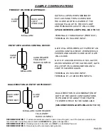
INPUT COMMANDS
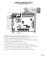
Control wire connections at low voltage terminal strip will be at the top of the electronic control board. Make
connections to the appropriate points for the desired operation. Wires should be U.L. approved 600 volt rated
and at least 18 awg. They are to be routed through the upper grommet in chassis to avoid chafing. All external
control devices must have normally open dry contacts.
DO NOT CONNECT ANY DEVICE WHICH WOULD
DELIVER ANY VOLTAGE OF ANY KIND TO THESE TERMINALS.
Terminals 9, 10, 11, 12 are the commons (0 VDC) used to activate the following inputs.
1, 2, 3 OPEN
-
These inputs will trigger gate open when pulsed or hold gate open with maintained contact.
When released gate will close if closing timer is on or if close input is given.
4, AUXILIARY OPEN
- Same as 1,2 and 3 with S2 switch 6 off. With S2 switch 6 on, this input will memorize
multiple vehicles and not allow gate to close until the final vehicle in memory crosses the close loop. Use with
laser scanners or card readers and (transmitters with timed anti-pass back). With S1 switch 5 on, this input
becomes a momentary
pulse open, pulse close.
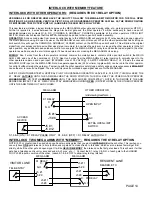
NOTE: Insert a jumper across the JP2 terminal to allow the interlock feature (see page 5 & 14) to work with the
multiple vehicle memory count selection, use the K1 relay to open the interlocked gate (S1-5 off, S2-6 on,
jumper across JP2). This allows gate to store input counts via J5 #4 but not raise the arm until the interlocked
slide or swing gate has fully opened.
5, SAFETY
- This input is generally not used with the MEGA-ARM. If used its function is to make gate reverse
and go back to the open position if it was closing. Input is disabled when gate is closed.
6, CLOSE
-
When used with a vehicle detector, it is recommended that the presence contacts (N.O. & C.) be
used for the close input. This input will close gate after input is applied and then removed. It will stop the open
cycle and reverse gate to close. (Example: Car crosses over close loop before arm reaches full open position-
gate will reverse and close). (Note: The close input also acts as a safety-stop in that if gate is closing and a
tailgater is sensed at the close input, the gate WILL STOP its closing motion and not continue to close until the
close input is removed or gate is re-opened).
PAGE 2


