


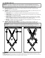


B. EXOFIT NEX™ CROSS-OVER STYLE FULL BODY HARNESS:
The ExoFit NEX™ Cross-Over Style
Harness incorporates loops for a removable waist belt. The belt can be installed through the two loops
in the harness located in the lower back shoulder straps (see Figure 10). The belt will pass through the
harness just below the padded area. The hip pad, if used, is secured to the belt by passing the belt
through the hip pad loops. Don the Cross-Over Style Full Body Harness per the following steps and
corresponding images in Figure 12:
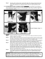
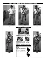
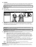
Step 1.
Locate the back D-ring held in position by the D-ring pad; lift up the harness and hold by
this D-ring. Ensure the straps are not twisted.
Step 2.
Grasp the shoulder straps between the back and front D-ring and slip the harness over your
head from the left side. Position the shoulder straps on top of your shoulders. Ensure that
the straps are not tangled and hang freely. The D-ring will be positioned on your back when
worn properly.
Step 3.
Grasp the tab of the buckle located at your right hip and insert it into the receptor of the
quick connect buckle (see Figure 12). You will hear a click when the tab engages properly.
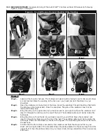
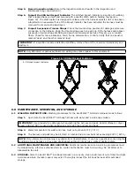
Step 4.
Reach between your legs and grasp the gray leg strap on your left side. Bring the strap up
between your legs and insert the tab of the buckle into the receptor of the buckle on the left
side as shown in Figure 12. You will hear a click when the tab engages properly. Connect
the right leg strap using the same procedure. To adjust the leg straps, unlock the webbing
lock on the quick connect buckle and pull on the strap. A plastic end keeper on the end of
the strap will stop it from pulling completely out of the buckle. When the strap is properly
adjusted, lock the webbing lock. To release the buckle, press the silver-colored tabs on the
buckle towards each other with one hand, while pulling on the tab portion of the buckle with
the other hand.
NOTE:
Locking and unlocking the webbing lock prevents or allows the strap to slide
between the sliding bar and slot on the female end of the quick connect buckle. It does
not control engagement or disengagement of the buckle ends and will not affect the
buckle connection in the event of a fall.
Step 5.
Adjust shoulder straps to a snug
fi
t with the Vertical Torso Adjusters (see Figure 12):
Left and right sides of the shoulder straps should be adjusted to the same length and the
front D-ring should be centered on your lower chest. The back D-ring should be centered
between your shoulder blades. Note: On ExoFit XP models, the back (dorsal) D-ring can
be repositioned up or down as needed for a correct
fi
t. Adjust the leg straps to a snug
fi
t.
At least 3 in. (8 cm) of webbing must extend past the buckle on the leg straps. Adjust the
waist belt (if present).
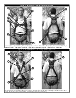
3.4 USE OF FALL ARREST D-RING OR ATTACHMENT ELEMENT:
For fall arrest applications connect to the
D-ring or attachment element on your back, between your shoulder blades. Side D-rings, if present, are for
positioning or restraint applications only. Front D-ring, if present, is for ladder climbing, positioning, or other
applications with a limited free fall not exceeding 2 feet (0.6 m) with a 900 MAF requirement. For rescue,
back, shoulder, or front D-rings may be used. D-rings on seat sling are for work positioning or personnel
riding.
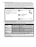
3.5 MAKING
CONNECTIONS:
When using a hook to connect to an anchorage or when coupling components
of the system together, ensure roll-out cannot occur. Roll-out occurs when interference between the hook
and mating connector causes the hook gate to unintentionally open and release. Self-locking snap hooks
and carabiners should be used to reduce the possibility of roll-out. Do not use hooks or connectors that
will not completely close over the attachment object. See subsystem manufacturer’s instructions for more
information on making connections.
3.6 CONNECTING SYSTEM COMPONENTS:
After properly
fi
tting the full body harness, the user may then
connect to other system components. Follow the guidelines in Section 3.4 when selecting the correct
attachment element.


