background image

2.9 MAKING 

CONNECTIONS:

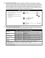
 Use only self-locking snap hooks and carabiners with this equipment. Only use 

connectors that are suitable to each application. Ensure all connections are compatible in size, shape and 

strength. Do not use equipment that is not compatible. Ensure all connectors are fully closed and locked.

 DBI-SALA connectors (snap hooks and carabiners) are designed to be used only as speci

fi

 ed in each 

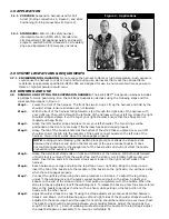
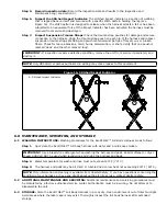
product’s user’s instructions. See Figure 7 for illustration of the inappropriate connections stated below. DBI-

SALA snap hooks and carabiners should not be connected:

A.  To a D-ring to which another connector is attached.

B.  In a manner that would result in a load on the gate.

C.  In a false engagement, where features that protrude from the snap hook or carabiner catch on the 

anchor and without visual con

fi

 rmation seems to be fully engaged to the anchor point.

D.  To each other.

E.  Directly to webbing or rope lanyard or tie-back (unless the manufacturer’s instructions for both the 

lanyard and connector speci

fi

 cally allow such a connection).

F.  To any object which is shaped or dimensioned such that the snap hook or carabiner will not close and 

lock, or that roll-out could occur.

G.  

In a manner that does not allow the connector to align with the fall arrest device (i.e., lanyard) while 

under load.

NOTE:

 Other than 3,600 lb. (16 kN) gated hooks, large throat opening snap hooks should not be 

connected to standard size D-rings or similar objects which will result in a load on the gate if the hook or 

D-ring twists or rotates. Large throat snap hooks are designed for use on 

fi

 xed structural elements such as 

rebar or cross members that are not shaped in a way that can capture the gate of the hook.

Other Restrictions:

Do not make connections where the hook locking mechanism can come into contact with a structural

member or other equipment and potentially release the hook.

Do not connect a snap hook into a loop or thimble of a wire rope or attach in any way to a slack wire

rope.

The snap hook must be free to align with the applied load as intended (regardless of the size or shape of

the mating connector).

A carabiner may be used to connect to a single or pair of soft loops on a body support such as a body

belt or full body harness, provided the carabiner can fully close and lock. This type of connection is not

allowed for snap hooks.

A carabiner may be connected to a loop or ring connector that is already occupied by a choker style

connector. This type of connection is not allowed for snap hooks.

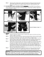
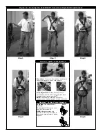
Figure 6 - Unintentional Disengagement (Rollout)

If the connecting element to which a snap hook (shown) or carabiner 

attaches is undersized or irregular in shape, a situation could occur 

where the connecting element applies a force to the gate of the snap 

hook or carabiner. This force may cause the gate (of either a self-

locking or a non-locking snap hook) to open, allowing the snap hook 

or carabiner to disengage from the connecting point.

Small ring or other 

non-compatibly 

shaped element

1.

Force is applied

to the Snap

Hook.

2.

The 

Gate

presses against

the Connecting

Ring.

3.

The Gate opens

allowing the

Snap Hook to

slip off.

Figure 7 - Inappropriate Connections

Summary of Contents for ExoFit NEX 1113283

Page 1: ...71 1113571C 1113572 1113572C 1113573 1113573C 1113574 1113574C 1113575 1113575C 1113576 1113576C 1113577 1113577C 1113578 1113578C 1113579 1113579C 1113580 1113580C 1113590 1113590C 1113591 1113591C 1...

Page 2: ...ab into the receptor of the quick connect buckle on the left side of the harness You will hear a click when the tab engages properly NOTE Locking and unlocking the webbing lock prevents or allows the...

Page 3: ...ect buckle ends by inserting the tab into the receptor until a click is heard Strap Adjustment Rotate Webbing Lock to unlocked position Pull strap to adjust Rotate Webbing Lock to locked position NOTE...

Page 4: ...tioning Work Positioning Step 1 Work Positioning Step 2 Work Positioning Step 3 Work Positioning Step 4 Work Positioning Step 5 Proceed to Figure 6 steps 1 6 Figure 4 Step 1 Suspend the harness by hol...

Page 5: ...left side of the belt into the quick connect buckle of the strap You will hear a click when the tab engages properly Step 4 Reach between your legs and grasp the leg strap on your right side Bring the...

Page 6: ...the D Ring loop Step 3 Bring the strap on the right side of your back around to your right hip Open the carabiner and insert it through the red loop on the top of the belt The carabiner gate must not...

Page 7: ...ust shoulder straps to a snug fit Before use adjust the harness leg straps to a snug fit At least 3 in 8 cm of webbing must extend past the buckle on the leg straps Adjust the waist belt again as nece...

Page 8: ...the product identification information from the ID label in the inspection and maintenance log in Section 9 of this manual DESCRIPTIONS The ExoFit NEX Full Body Harness is available in Vest Figure 1 a...

Page 9: ...ID Tag Labels E Revolver Torso Adjustor F Tech Lite Side D Ring G Leg Strap H Tech Lite Dorsal D Ring I Trauma Strap Figure 2 ExoFit NEX Cross Over Style Full Body Harness A B C D E F G A Shoulder Str...

Page 10: ...access confined space applications harnesses equipped with D rings on the shoulders may be used for entry and egress into confined spaces where worker profile is an issue Ladder Climbing Class L The...

Page 11: ...ns with a combined weight clothing tools etc of no more than 420 lbs 191 kg per OSHA 310 lbs 141 kg per ANSI Z359 1 or 352 lbs 160 kg per CSA Z259 10 06 Make sure all of the components in your system...

Page 12: ...extended length of time it is recommended that some form of seat support be used DBI SALA recommends a seat board suspension work seat seat sling or a boatswain chair Contact Capital Safety for more i...

Page 13: ...e if the hook or D ring twists or rotates Large throat snap hooks are designed for use on fixed structural elements such as rebar or cross members that are not shaped in a way that can capture the gat...

Page 14: ...1 anchorages selected for Fall Arrest Systems must meet the anchorage strength requirements defined in Table 2 Table 2 Anchorage Strength Requirements Fall Arrest1 Non Certified Anchorages 5 000 lbs...

Page 15: ...arrest forces as described in Section 5 must be removed from service immediately and destroyed by the user the rescuer1 or an authorized person2 RESCUE The employer must have a rescue plan when using...

Page 16: ...g lock To release the buckle press the silver colored tabs on the buckle towards each other with one hand while pulling on the tab portion of the buckle with the other hand NOTE Locking and unlocking...

Page 17: ...ing Lock to unlocked position Pull strap to adjust Rotate Webbing Lock to locked position NOTE The Webbing Lock does not control engagement or disengagement of the buckle ends Revolver Vertical Torso...

Page 18: ...ocking the webbing lock prevents or allows the strap to slide between the sliding bar and slot on the female end of the quick connect buckle It does not control engagement or disengagement of the buck...

Page 19: ...ate Webbing Lock to unlocked position Pull strap to adjust Rotate Webbing Lock to locked position NOTE The Webbing Lock does not control engagement or disengagement of the buckle ends Revolver Vertica...

Page 20: ...sition following suspension Do not lay down Seek medical attention following a suspension Figure 13 Suspension Trauma Straps A B 3 8 EXOFIT NEX GLOBAL WIND ENERGY HARNESS MODEL REPLACEABLE LUMBAR PROT...

Page 21: ...ed use etc may require increasing the frequency of inspections 5 3 INSPECTION Inspect the ExoFit NEX Full Body Harness as follows Step 1 Inspect harness hardware buckles D rings pads loop keepers vert...

Page 22: ...iting may make repairs to this equipment Figure 16 Stitched Impact Indicator A Stitched Impact Indicator A A 6 0 MAINTENANCE SERVICING AND STORAGE 6 1 WASHING INSTRUCTIONS Washing procedures for the E...

Page 23: ...IALS Webbing Materials 6 000 lbs 27 kN Polyester 7 000 lbs 31 kN Tensile Strength Nylon 7 000 lbs Tensile Strength Nomex4 covered Kevlar4 Pad and Label Cover Materials Blend of Nylon and Polyester All...

Page 24: ...INSPECTION DATE INSPECTION ITEMS NOTED CORRECTIVE ACTION MAINTENANCE PERFORMED Approved By Approved By Approved By Approved By Approved By Approved By Approved By Approved By Approved By Approved By A...

Page 25: ...SPECTION DATE INSPECTION ITEMS NOTED CORRECTIVE ACTION MAINTENANCE PERFORMED Approved By Approved By Approved By Approved By Approved By Approved By Approved By Approved By Approved By Approved By App...

Page 26: ...SPECTION DATE INSPECTION ITEMS NOTED CORRECTIVE ACTION MAINTENANCE PERFORMED Approved By Approved By Approved By Approved By Approved By Approved By Approved By Approved By Approved By Approved By App...

Page 27: ...1113336 1113337 1113338 1113339 1113345 1113346 1113347 1113348 1113350 1113351 1113352 1113353 1113354 1113355 1113356 1113357 1113358 1113359 1113360 1113361 1113362 1113363 1113364 1113365 1113366...

Page 28: ...3433C 1113440C 1113441C 1113442C 1113449 1113450 1113451 1113452 1113453 1113454 1113455 1113456 1113457 1113458 1113459C 1113460C 1113467C 1113468C 1113509C 1113510C 1113511C 1113512C 1113513C 111351...

Reviews: