background image

3

S

ETUP AND

/

OR

O

PERATING

C

ONSIDERATIONS

3.a S

ETTING A

10A18-4C C

HANNEL FOR

F

OUR

-W

IRE OR

T

HREE

-W

IRE

RTD C

ABLING

When the Model 10A18-4C is shipped, all four channels are normally set for the four-
wire 
RTD cabling shown in Fig. 1(a), above, since this mode of cabling normally yields
the highest accuracy.  If you wish to use the three-wire cabling shown in Fig. 1(b) for a
given 10A18-4C channel, you should

1.

Remove the 10A18-4C card from its mainframe slot.  For “Card Insertion and
Removal,” see Manual Section 1.B.  Since the 10A18-4C is “hot-pluggable,” you
need NOT turn off mainframe power before removing the card.

2.

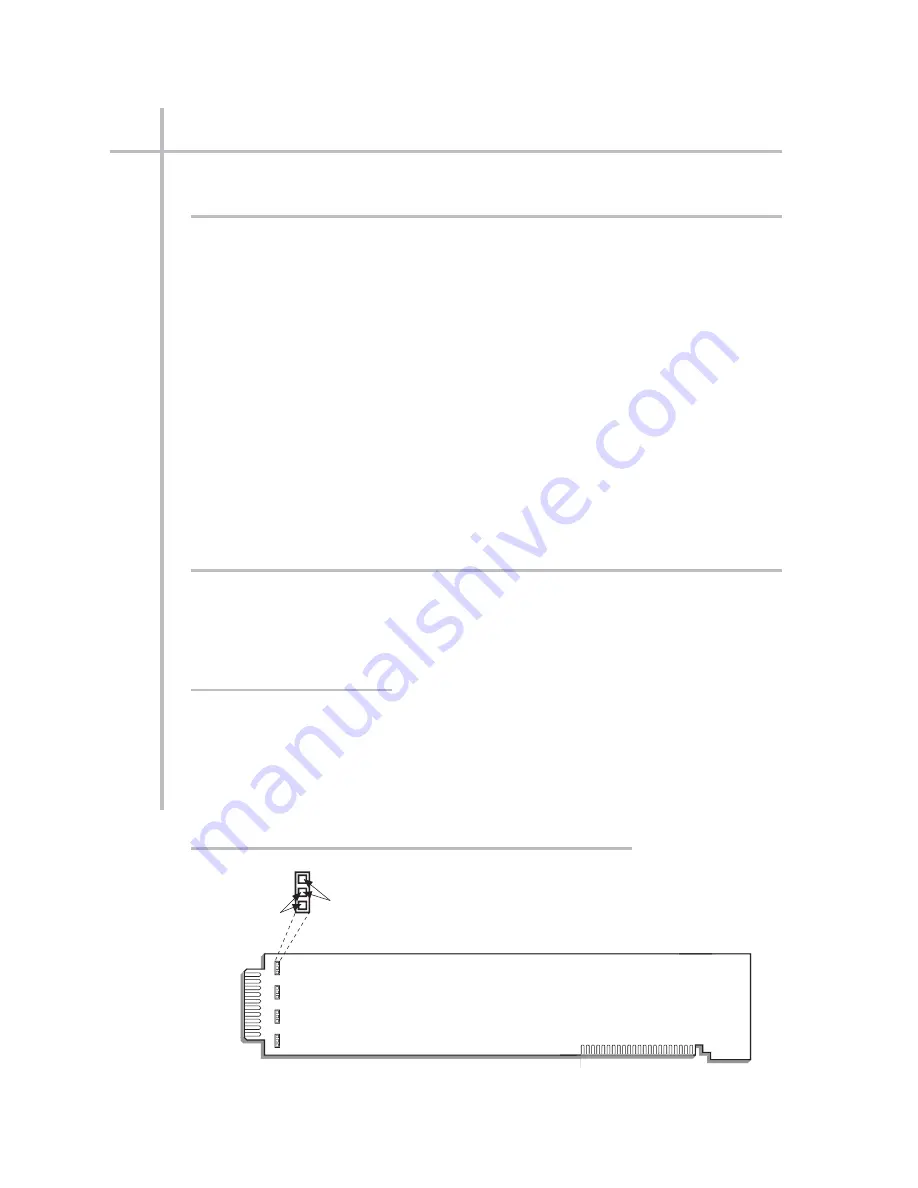
Refer to Fig. 3, below, and locate the four sets of “RTD CABLING” PROGRAMMING
JUMPER PINS, one for each channel, on the top (component) side of the card.
One “minijumper” is provided for each channel, for interconnecting any two adja-
cent jumper pins.

3.

Position the jumper for each active channel as shown in Fig. 3 to set the desired
wiring mode for that channel.

4.

Reinsert the 10A18-4C card into its mainframe slot.

3.b C

ONFIGURATION AND

C

ALIBRATION

For initial configuration of ANALOG INPUT CHANNELS dedicated to a specific Model
10A18-4C card when used in System 10, see the following section, along with the gen-
eral remarks on System 10 “real-channel” configuration in Manual Section 1.G.1 and
elsewhere in the System 10 Guidebook.

C

ALCULATED

C

ALIBRATION

In System 10, the initial configuration and 

CALCULATED CALIBRATION

of a 10A18-

4C channel (No. “x”) involve direct entry of the channel’s TYPE CODE, SCALING FAC-
TOR (“m” coefficient), and ZERO OFFSET (“b” term) via the corresponding mnemonic
commands.  The values of these parameters that are entered will depend on the RTD
type, range, and desired engineering units (°C or °F), as given in Table 2, below.  For

S

ETUP AND

/

OR

O

PERATING

C

ONSIDERATIONS

10A18-4C.

5

Q

UAD

P

LATINUM

L

INEAR

RTD C

ARD

10A18-4C

Side 2

Rear I/O Connector

Channel 1

Connect these pins 
for THREE-WIRE 
RTD CABLING

Channel 2

Channel 3

Channel 4

Connect these pins 

for FOUR-WIRE 

RTD CABLING

Fig. 3  10A18-4C “RTD CABLING” Programming Jumper Pins

Summary of Contents for System 10

Page 1: ...Signal Processing Instrumentation for Measurement Analysis User s Guidebook VersionSB 8 Stand Alone MODULARFRONTEND DataAcquisition Control 10 SYSTEM...

Page 2: ...change without notice PLEASE NOTE the following section and figure reference corrections for Sections 2 3 and 5 of this Guidebook When you are You should told to refer to actually refer to Section 1 B...

Page 3: ...ying System 10 If you have any questions or problems please don t hesitate to call our CUSTOMER SUPPORT SERVICES or our SALES APPLICATIONS STAFF at 937 293 2566 FAX 937 293 2586 TOLL FREE 800 668 4745...

Page 4: ...A 19 13 Limit Setup A 20 14 Setup of EXECUTE Functions A 23 15 Setting Data Transmission Characteristics A 25 16 Communication with External Devices a Introduction System 10 Communication Modes A 26...

Page 5: ...f IEEE 488 Communications B 38 f Setup of RS 422 Communications B 38 17 Optional Bargraph Setup Model 10VGM500 B 39 18 Optional History Recording Model 10BDR64 B 42 19 Further Optional Procedures B 48...

Page 6: ...rating Considerations a Programming Open TC Detection 10A9 8C 5 b Configuration and Calibration 10A9 8C 5 4 Optional Remote TC Connections Model 10CTJB 8 Thermocouple Junction Box a Purpose 10A9 8C 6...

Page 7: ...4C 5 Two Point Deadweight Calibration 10A18 4C 7 Model 10A30 2C Dual LVDT Conditioner Card 1 General Description and Specifications 10A30 2C 1 2 Transducer Connections 10A30 2C 2 3 Setup and or Opera...

Page 8: ...Conditioner Card 1 General Description and Specifications 10A43 1 2 Transducer Connections 10A43 2 3 Setup and or Operating Considerations a Configuration and Calibration 10A43 3 Model 10A45 Simmonds...

Page 9: ...libration 10A63 2 5 Model 10A64 8C Eight Channel Voltage Conditioner Card 1 General Description and Specifications 10A64 8C 1 2 Transducer Connections 10A64 8C 2 3 Setup and or Operating Consideration...

Page 10: ...Calculated Calibration 10A72 2C 11 Two Point Deadweight Calibration 10A72 2C 11 Simulated Shunt Calibration 10A72 2C 11 Coarse Zero Offset 10A72 2C 11 Model 10A73 4 1 2 1 4 Bridge Strain Gage Conditi...

Page 11: ...aptor with the Model 10A74 4C 10A74 4C 16 Absolute Calibration 10A74 4C 16 Two Point Deadweight Calibration 10A74 4C 17 Model 10A76 Vibration Conditioner Card 1 General Description and Specifications...

Page 12: ...AA41 2 AA41 4 Frequency Input Conditioner Card 1 General Description and Specifications AA41 2 4 1 2 Transducer Connections a Standard Cabling AA41 2 4 4 b Special Cabling Ungrounded Frequency Source...

Page 13: ...NELS 1 Setup of Real Analog Input Channels TYP and LCT 1 33 2 Methods of Calibration 1 34 3 Absolute Calibration a CPU Based Absolute Calibration 1 35 b Absolute Calibration for a Frequency Current or...

Page 14: ...Interfacing b OR Connection Daisy Chaining of Two RS 232 C Devices to a Single DataPAC or of two DataPACs to a Single RS 232 C Device c Switched Connection of Two RS 232 C Devices to a Single DataPAC...

Page 15: ...d Video Playback Field 2 Bit State Field 3 Message Field d Cursor Movement Arrow Keys e Repeated Character Entry f Insertion and Deletion of Fixed Text Spaces Insert and Delete Keys 1 Space Insertion...

Page 16: ...EEN STATUS VBT and LESS THAN STATUS VLT Commands 3 Temporary External Control of Data Field Status STS Command 4 Setting Visual Effects for Time and Date Channels VBT Command c Setting Visual Effects...

Page 17: ...Limit Logic 1 Latching Limit Logic 2 Nonlatching Limit Logic b Logic Input c External Bit Control 1 Temporary Run Time External Control BIT BIN BCD and HEX Commands a Setting and Reading a Single Bit...

Page 18: ...ommand Queues CSB and PSB Commands e Powerup Delay of Execute Functions EXM Command f Disabling All Execute Functions NOB and BTS Commands 3 The COMMAND CMD Command a Specifying Conditional Bits CDL C...

Page 19: ...ing Page Type PGT Commands b Setup of an XY Page 1 Defining Page List PGL Command 2 Setting Graph Scales GRX and GRY Commands 3 Setting Graph Legends LEG Command c Setup of a Strip Chart Page 1 Defini...

Page 20: ...Port Configuration 2 S OPTIONAL OPERATOR S KEYBOARDS MODELS 10P25A AND 10P25D 1 Introduction 2 Keyboard Functions a Key Prompts FNCTN Key b LCD Billboard Scroll ARROW Keys c Clearing LCD Billboard CL...

Page 21: ...COR and COC Commands 3 A 2 VOLTAGE AND CURRENT OUTPUTS MODEL 10AAO 8 AND MODEL 10CAI 8 a Introduction b Setup of 5 Volt Outputs 1 Model 10AAO 8 Connections 2 Configuration of Analog Output Channels a...

Page 22: ...hannel Mode 3 Configuring and Calibrating MAX MIN Subchannels c MAX MIN Operation 1 Tracking the Analog Input 2 MAX MIN Measurement 3 Inversion of MAX MIN Polarity EMM Command 4 Holding a MAX MIN Subc...

Page 23: ...itiating Data Transmissions in Gated Output Mode a Destructive Data Output DDO Command b Nondestructive Data Output NDO Command 2 Halting and Restarting 10AFIFO Transmissions 3 Bypassing the 10AFIFO M...

Page 24: ...nds a BCD Output to Represent a Fixed Decimal Value b BCD Output to Represent the Value of a Data Channel c Cancelling the BCD Command BIT Command 4 BCD Input CHN Command 3 B 3 SATELLITE NETWORK SYSTE...

Page 25: ...DataPAC Node GBL Command 5 Explicit Routing of Global Commands a Opening a Direct Command Route Between Any Two Network Nodes OPN Command b Routing a Single Command Between Any Two DataPAC Nodes NOD...

Page 26: ...acks RSP Command f Cancelling Playback Assignments PLA and RST Commands 9 Setting Up Playback of System Bit Groups CHN PLA CCH and BIN Commands 10 Formatting Recorder Outputs IMA Command e History Car...

Page 27: ...IA New Features 1 Ensuring 10BACIA Central Processor Compatibility BCP Command 2 Transmitting a Time Coherent Data Frame FCH Command 3 The MTC Command 4 Response to DSD Command 3 B 5 Supplement No 2 M...

Page 28: ...ng a Carriage Return 3 Clearing a Queue of Video Pages CLQ Command d Formatting of Page Printouts 1 Specifying End of Line Control Character s EOL Command 2 Specifying End of Page Control Character s...

Page 29: ...n Conditionals 3 Setting Button Executes d Highlighting and Disabling Buttons on a Page 1 Setting Button Highlight Color BFC Command 2 Highlighting Page Buttons SBL Command 3 Disabling Page Buttons CL...

Page 30: ...nd has been removed C DATA CHANNEL RECONFIGURATION TYP LCT AND RST COMMANDS 1 Uses of the RESET RST Command 2 Data Channel Reconfiguration 3 System 10 Channel TYPE Codes D NOTE This appendix has been...

Page 31: ...GETTING YOUR SYSTEM 10 ON THE AIR SB 2 FOR A SIZED MAINFRAMES...

Page 32: ...ed reproduced or used in any form or by any electronic mechanical or other means including photocopying and recording or in any information storage and retrieval system without permission in writing f...

Page 33: ...THE AIR FOR A SIZED MAINFRAMES On the Air A Sized v SB 2 Pub No 10KOAA 2 Issued 11 01 Part No 91777 Daytronic Corporation 2211 Arbor Blvd Dayton OH 45439 1521 Tel 937 293 2566 Fax 937 293 2586 800 66...

Page 34: ...Setup of Cross Channel Calculations 16 12 Setup of Logic Bits and Logic Ports a Sourcing of Logic Bits 18 b Initialization of Optional Model 10AIO 16 19 13 Limit Setup 20 14 Setup of EXECUTE Function...

Page 35: ...setup pro cedures along with some essential background information Its only purpose is to GET YOU STARTED 1 b A SIZED MAINFRAMES AND EXTENDED KEYBOARDS There are two basic types of System 10 mainframe...

Page 36: ...s case you will need to set up your mainframe s Computer Interface Port before any other procedures are performed Turn now to Section 2 B of your System 10 Guidebook and follow the interface setup ins...

Page 37: ...232 Protocol Switch es of a mainframe of the 10K1 10K2 family you will have to remove the front bezel by gently prying it off the snap on posts that secure it to the mainframe For the other A sized ma...

Page 38: ...tional A Cards Central Processor Interface Card Interface Protocol Switches are mounted on this board Snap On Front Bezel Post A SLOT No 1 Plug In Keyboard Connector Front Panel Large Scale LCD VFD Di...

Page 39: ...splay Optional A Cards Front Panel Large Scale LCD VFD Display Model 10K4T D 10K4T DA only Power ON OFF Switch Fuse AC Power Connector Voltage Selector Switch Plug In Keyboard Connector Interface Prot...

Page 40: ...el LCD or VFD display it will normally display Page Format No 1 Channels 1 through 12 with legends of MVV when first powered up The display billboard whether on the mainframe or a connected 10P80D key...

Page 41: ...Switch by placing it in the upward position An alternative method for enabling the EEPROM Write Pro tect function especially useful when you don t want to have to remove the front bezel to access the...

Page 42: ...isplay you will set up Display Page No 13 to display Data Channel Nos 1 2 3 4 5 7 10 28 119 121 998 and 999 in that order If it is an 8 line VFD display you will set up this page to display Data Chan...

Page 43: ...G 4 SPACE CR A channel s displayed unit legend can have up to four alphanumeric charac ters any or all of which may be spaces For an LCD display Channels 998 TIME and 999 DATE do not take legends 6 SE...

Page 44: ...of mainframe 10A Conditioner Card 20 Pin Conditioner Connector No 60322 Pin 1 Pin A Pin 10 Pin L Cables to Transducers Cable Clamp Bar Screws Captive Screw for mounting to mainframe Connector Keys to...

Page 45: ...he mainframe etc Configuration of a real channel ordinarily involves applying to that channel first a TYPE TYP command and then a LOCATE LCT command In the following procedure however you will simply...

Page 46: ...DE shown on the data sheet for Channel No 1 should now appear in the billboard region of the mainframe or keyboard display A channel s type code specifies one or more special pro cessing factors that...

Page 47: ...m 10 s initial default scan range is normally preset at the factory The typical range is from Channel No 1 through the highest Channel Number called for by the system configuration specified at the ti...

Page 48: ...ANNEL CALIBRATION The purpose of this section is to lead you step by step through a typical Sys tem 10 real channel calibration As explained in Section 1 G 2 of the System 10 Guidebook a number of dif...

Page 49: ...o 1 unless you have already specified a new channel list for this page if x is from 13 through 24 it should appear on Page No 2 etc If your mainframe does not have a multichannel LCD or VFD display yo...

Page 50: ...System 10 Guidebook shows you how to set a data channel s SCALING FACTOR and ZERO OFFSET directly using the SCALING FACTOR EMM and OFFSET BEE commands respectively Section 2 G also tells you how to se...

Page 51: ...0 assumed in the above command to 1 type CLC y 2 0 CHN x 1 0 CR The reading of Channel No y should now equal twice the reading of Chan nel No x plus one Note that the offset or b term of the CALCULATE...

Page 52: ...t Ports Before you set any logic sources however you must learn to use the SET BIT BIT command to set and read system logic bit states 1 You may disable the EEPROM Write Protect function if you want t...

Page 53: ...O PORTS are to be INPUTS and which are to be OUTPUTS you must first initialize the 10AIO 16 card You will use the A SLOT ASL command to establish a one to one correspondence between the 10AIO 16 s si...

Page 54: ...ther logic bit using the LESS THAN LOGIC LLT command release a latched bit using the RELEASE RLS command cancel a channel s existing GREATER THAN and LESS THAN LOGIC using the LGT and LLT commands a T...

Page 55: ...an answer of 898 1 indicating the presence of the GREATER THAN limit violation for Channel No x g Decrease the transducer load until it is less than the high limit value but higher than the low limit...

Page 56: ...ayed with Channel No x s data reading point downward as soon as the low limit is violated m Use the READ form of the BIT command see Step d above to check the state of Bit No 899 You should now get an...

Page 57: ...an arbitrary numeric constant 2 You must there fore assign it a TYPE CODE of D0 D zero by entering a TYPE TYP command of TYP 150 D0 CR for a full discussion of Downloading of Numeric Data see Section...

Page 58: ...97 0 CR l Keep the high violation load on the transducer and enter a command of EXU r CHN150 25 BIT897 1 CR where r is again the number of the selected trigger bit This command instructs the system to...

Page 59: ...ON CHARACTERISTICS Your system can be made to transmit different kinds of data from its COM PUTER INTERFACE PORT including numerical values contained in system DATA CHANNELS whether these values repre...

Page 60: ...k 16 COMMUNICATION WITH EXTERNAL DEVICES 16 a INTRODUCTION SYSTEM 10 COMMUNICATION MODES Every A sized System 10 mainframe has a single COMPUTER INTERFACE PORT This port allows two way communication w...

Page 61: ...r Interface Port must be set to conform exactly with the protocol stipulated by the connected device The protocol applying to an RS 232 C link normally involves four basic data transfer characteristic...

Page 62: ...id entry of up to five selected System 10 commands Specifically it allows any standard three letter MNEMONIC to be communicated to the mainframe by pressing the keypad s FNCTN FUNCTION key and then th...

Page 63: ...Section 3 A 3 setup of ANALOG PEAK CAPTURE MAX MINUS MIN and or TRACK AND HOLD functions when the optional Model 10A79 4 Four Channel Analog Peak Capture Card is present Sections 3 A 4 6 setup of ANAL...

Page 64: ...nded or operator s keyboard with 2 line billboard LCD 10P80D or 10P25D 10K2D 20 160 160 1000 320 Integral front panel multichannel VFD display extended keyboard 10P80A supplied operator s keyboard 10P...

Page 65: ...MMARY OF A SIZED MAINFRAME FEATURES Options S Satellite required for Model 10BD4 based networks V Vehicle Operation 12 or 28 V DC 1 Up to 1000 channels can be handled when the S Satellite Option is pr...

Page 66: ...Daytronic Corporation 2211 Arbor Blvd Dayton OH 45439 1521 800 668 4745 Tel 937 293 2566 Fax 937 293 2586 www daytronic com...

Page 67: ...GETTING YOUR SYSTEM 10 ON THE AIR SB 2 FOR B SIZED MAINFRAMES...

Page 68: ...ed reproduced or used in any form or by any electronic mechanical or other means including photocopying and recording or in any information storage and retrieval system without permission in writing f...

Page 69: ...THE AIR FOR B SIZED MAINFRAMES On the Air B Sized v SB 2 Pub No 10KOAB 2 Issued 11 01 Part No 91778 Daytronic Corporation 2211 Arbor Blvd Dayton OH 45439 1521 Tel 937 293 2566 Fax 937 293 2586 800 66...

Page 70: ...s 30 b Setup of CONDITIONAL and COMMAND Functions 32 15 Setting Data Transmission Characteristics 33 16 Communication with External Devices a Introduction System 10 Communication Modes 34 b Setup of M...

Page 71: ...ort form manual but rather a simplified presentation of selected but basic setup pro cedures along with some essential background information Its only purpose is to GET YOU STARTED 1 b B SIZED MAINFRA...

Page 72: ...motely You issue commands locally by typing them on the Model 10P80A Extended Keyboard supplied with your B sized mainframe You issue com mands remotely by using an EXTERNAL COMPUTER OR TERMINAL to de...

Page 73: ...ew drawings below to familiarize yourself with your mainframe s most important physical elements Be sure that you know the locations of your particular mainframe s B Rack and B Cards including Central...

Page 74: ...acket Internal Monochrome Monitor Internal CRT Controls Optional A Cards A SLOT No 24 Actuating Lever A SLOT No 1 Model 10KN7 mainframes only On mainframes with the E Extended B Rack Option the CRT sp...

Page 75: ...requires optional Model 10VFO132 Formatted Output Card for operation RS 232 Touchscreen Connector Removable A Slot Cover A Card I O Connectors for connection of transducers and control I O VGA Input V...

Page 76: ...d Interface Protocol Switches are also mounted on this board Central Processor Card Plug In Keyboard Connector Optional B Cards B Slot Nos 5 6 Brightness Control Contrast Control Video Signal Card occ...

Page 77: ...A Card I O Connectors for connection of transducers and control I O VGA Input VGA Output Video Connector Panel NOT TO BE REMOVED Combined Power ON OFF and Circuit Breaker Button Replaceable Fan Filte...

Page 78: ...fy proper system powerup Also the words RAM TEST PASSED may appear for about two seconds in the billboard region of your mainframe s CRT display to be immediately replaced by your company s name or ot...

Page 79: ...ine during the measurement and control process Video pages can also be transmitted to the computer line by line for storage in the computer s own memory See Section 2 C 11 of the System 10 Guidebook f...

Page 80: ...o each stored page and which pages if any are contained in the memory extension provided by an optional Model 10VGM500 It also shows after the words PAGE DIRECTO RY the free video memory available in...

Page 81: ...page we now wish to compose The first screen a shows the page format while still in TEXT EDI TOR MODE the user entered data fields are still occupied by channel number entries The second screen b sho...

Page 82: ...srt INSERT key once This inserts one white background space to the left of the word WARNING at the position of the cursor 6 Now reset the color of this inserted space to white on black SHIFT WHITE BAC...

Page 83: ...for details 16 Now enter the remaining FIXED TEXT for this line one space followed by the unit legend IN HG Since the whole line was inserted in Step 11 with the foreground background combination spec...

Page 84: ...d by Retrn The appropriate response PAG n should appear in the billboard o Press Retrn once more and note the logo text presently in the display bill board Change the logo to ABC CORP by typing LGO AB...

Page 85: ...0 pin connector for a Daytronic AA Conditioner Card with labelled screw terminals for direct connection of transducer cable leads If you re supplying your own sensor cables you should carefully read S...

Page 86: ...NALOG OUTPUT CHANNELS PSEUDOCHANNELS and CONVERSION CHANNELS You need not worry about these other types of channels right now NOTE IN ALMOST ALL CASES YOUR SYSTEM S ANALOG INPUT CHANNELS WILL HAVE BEE...

Page 87: ...d to CALCULATION and or ANALOG OUTPUT functions It lists all EXECUTE CONDITIONAL and COMMAND statements that have been pre entered for your system as well as all LOGIC SOURCE and BIT DESIGNATOR assign...

Page 88: ...d deck will always be the highest numbered The second and third location digits represent the A SLOT NUMBER within the given deck for the A CARD that handles the given channel Each deck can have up to...

Page 89: ...e location value of your live real channel in the LCT column Note the corresponding CHANNEL NUMBER in the Channel CHN column We will call this number x d Now enter a command of TER t2 CR where t2 is a...

Page 90: ...brate a signal conditioner channel by com manding the system s Central Processor to compute and store two constant values a SCALING FACTOR m and a ZERO OFFSET b Automatically and continuously applied...

Page 91: ...function is enabled and enter from the keyboard a command of ZRO x CR The displayed value for Channel No x should now be zero If it is not recheck the transducer connection the channel number and the...

Page 92: ...are root absolute value maximum most positive value and minimum least positive value They permit real time computation of such process vari ables as Efficiency Horsepower Specific Fuel Consumption Pow...

Page 93: ...his term was entered as 1 0 res olution will be to the nearest tenth of a unit Note also that we changed the decimal point location of the gain or m coefficient of the CALCULATE expression from 2 to 2...

Page 94: ...t Ports Before you set any logic sources however you must learn to use the SET BIT BIT command to set and read system logic bit states 1 You may disable the EEPROM Write Protect function if you want t...

Page 95: ...be INPUTS and which are to be OUTPUTS you must first initialize the 10BIO 16 card You will use the B SLOT BSL command to establish a one to one correspondence between the 10BIO 16 s sixteen Logic I O...

Page 96: ...a BIT STATE FIELD for CRT display of a given logic bit arrange for a data channel s HIGH LIMIT violation to set a given system logic bit using the GREATER THAN LOGIC LGT command arrange for a LOW LIMI...

Page 97: ...with red characters on a blue background 3 enter a command of VGT x BRF CR h Verify the effectiveness of the above VGT command by producing an approximately full scale transducer input and observing...

Page 98: ...stem 10 Guidebook 9 Save the page you have just formatted as you did in Section 5 Step l In Section 12 a above you used the SRC command to assign a logic source of LATCHING LIMIT LOGIC to Bit No 898 N...

Page 99: ...on 12 a Step 7 above REMEMBER The reference to any logic bit by one of the three LIMIT LOGIC commands LGT LLT or LBT automatically sets the source of that bit to NONLATCHING LIMIT LOGIC o Verify the e...

Page 100: ...el No 900 to be a DOWNLOAD PSEUDOCHANNEL so that we can load it with an arbitrary numeric constant You must there fore assign it a TYPE CODE of D0 D zero by entering a TYPE TYP command of TYP 900 D0 C...

Page 101: ...annel should report a value of 0 11 Now enter a command of BIT 898 0 CR 12 Call to display the video page you composed in Section 13 Step i above for the live display of Bit Nos 898 and 899 Verify tha...

Page 102: ...s are not to be confused with your system s 1000 LOGIC BITS whose states are determined by various logic sources as explained in Section 12 a The state of a CONDITIONAL BIT is determined solely by the...

Page 103: ...not already read HIGH enter a command of BIT 899 1 CR 4 To obtain the second required condition for execution of the above CMD command increase the load applied to Channel No x s source transduc er un...

Page 104: ...s the single ASCII character recognized by your system as the termination of any com mand received through the Computer Interface Port It is always set initial ly to CARRIAGE RETURN CR or in hexadecim...

Page 105: ...ons are required by your applica tion Two special 10BACI versions permit auxiliary IEEE 488 and RS 422 interfacing respectively independent of the main Computer Interface Port When equipped with a Mod...

Page 106: ...three run time com mands you should be aware of 3 Discussed in detail in Section 3 B 5 of the System 10 Guidebook these commands are used for control of the Auxiliary Computer Interface the ACI eithe...

Page 107: ...you must issue a BAUD RATE BAU command to the 10BACIA that provides the interface after attaching the 10BACIA to your command source by means of the ATT or VIA command The form of the BAU command for...

Page 108: ...data channels along with optional header and tailer texts which are actually separate precomposed video pages The TEMPLATE TMP command lets you create a unique template for the presentation of transm...

Page 109: ...WITH SCALE First you will speci fy the bargraph s size its position on the page and the individual data chan nel it is to represent Then prompted by a screen menu you will enter the bargraph s type an...

Page 110: ...using one or two leading zeros if necessary 2 Remember that the last digit of the channel number entry must always occupy the last character space of the bargraph field m Press the End Data key The fi...

Page 111: ...if you wish see Section 5 Step l u The colors now exhibited by your live bargraph are continuously deter mined by the VISUAL EFFECTS you have already specified for Channel No x by the LESS THAN STATU...

Page 112: ...ss shutdown You can select variables to appear in a recorder s output such as time date seri al number etc and the order in which these variables are to be transmitted The History Card lets you play b...

Page 113: ...NOT WANT OR NEED TO PERFORM THE FOLLOWING PROCEDURES IF YOU DO CHOOSE TO PERFORM THE FOL LOWING PROCEDURES BE SURE TO CLONE THE CURRENT HISTORY CARD CONFIGURATION BEFORE PROCEEDING ANY FURTHER YOU CA...

Page 114: ...ion of the STO command in Section 3 B 4 d and to experiment with different conditions for automatic recording and storage of data for example when a given bit is perceived to go high when a given chan...

Page 115: ...all to display the prestored blank video page no 100 2 Press the Video Formt VIDEO FORMAT key to enter TEXT EDITOR MODE Move the cursor down a few spaces 3 Type 01 Frames Ago and then press the Begin...

Page 116: ...before halting the automatic recording of data Verify that this is the case by watching your playback display as you continue to vary the load on the source transducer for Channel No x m Use the BIT c...

Page 117: ...MP command is normally used while recording is in process It lets you learn what has happened since the last such interro gation You can use this command to output from the Computer Interface Port all...

Page 118: ...ture Card or Model 10AAO 4 Analog Buffer Card is present Section 3 A 7 setup of PID LOOP CONTROL functions when the optional Model 10APID Loop Control Card is present Section 3 A 9 setup of DIGITAL I...

Page 119: ...000 768 1000 128 10KN8A 8 2 1000 64 1000 32 Internal CRT COLOR 12 multi sync CGA EGA VGA VGA input and output6 2 available V Card slots SUMMARY OF B SIZED MAINFRAME FEATURES B 49 Options E B Rack Expa...

Page 120: ...Daytronic Corporation 2211 Arbor Blvd Dayton OH 45439 1521 800 668 4745 Tel 937 293 2566 Fax 937 293 2586 www daytronic com...

Page 121: ...c com SECTION 1 A GETTING STARTED SECTION 1 B CARD INSERTION AND REMOVAL SECTION 1 C ENTRY OF MNEMONIC COMMANDS SECTION 1 D SYSTEM STATUS INDICATORS SECTION 1 E TRANSDUCER CABLING AND CONDITIONER CARD...

Page 122: ...THIS PAGE INTENTIONALLY BLANK...

Page 123: ...be ON only for the duration of relevant system SETUP procedures As soon as system setup including data channel calibration is complete be sure to TURN THE EEPROM SWITCH OFF During normal operation fol...

Page 124: ...HAS PROTECTIVE VELCRO ATTACHED MYLAR SHEETS WHICH SHOULD NEVER BE REMOVED Short circuiting of the battery could occur with possible severe damage to the instrument e AIR COOLING REQUIREMENTS ALL MAIN...

Page 125: ...Changing the Fuse below B SIZED MAINFRAMES For all B SIZED mainframes except the Model 10KN8A the POWER SELEC TOR BOARD is located under the fuse see Fig 2 1 b in the Physical Layout section of the On...

Page 126: ...om a two contact outlet use a 3 prong to 2 prong adaptor and con nect the green pigtail on the adaptor to earth ground NOTE Since the presence of electrical noise can affect the ultimate integrity of...

Page 127: ...1 As explained in Section 5 of the On the Air book for B sized mainframes you can subsequently redesign the format of this video page if desired and designate any other video page to be the mainframe...

Page 128: ...e proper connector pins These are clearly marked on the main frame s rear label Although all V units are protected against accidental polarity reversal they naturally will not work under that conditio...

Page 129: ...for A sized mainframes see Appendix A of the On the Air book b DISPLAY SETTINGS FOR B SIZED MAINFRAMES The following commands are used for initial general setup of a B sized main frame s CRT video di...

Page 130: ...el 10BVS98 VGA Video Signal Card in a Model 10KN3 10KN6 or 10KN8A mainframe is preset at the factory for normal VGA mode with invert ed vertical and horizontal sync If you need to change either or bot...

Page 131: ...ntly prying it off its Snap On Posts see the respective front element figure in Section 2 of the On the Air book for A sized mainframes For a B sized mainframe you will remove the bezel by pulling dow...

Page 132: ...slot remove the card and examine the slot for any foreign object that may be impeding the insertion also check the card itself for any compo nent s that may be catching on an adjacent card g Align th...

Page 133: ...ely screwed to the mainframe before you pull the card out of the slot Otherwise the connector and its cable will simply fall off the rear of the unit as soon as it disengages from the card IMPORTANT A...

Page 134: ...1 12 THIS PAGE INTENTIONALLY BLANK...

Page 135: ...play or for transmission from a sys tem SERIAL INTERFACE PORT 4 IMPERATIVE COMMANDS As a rule these command do not actually enter or request information but rather instruct the system to do something...

Page 136: ...ECUTE EXU and COMMAND CMD statements for automatic applica tion of commands is discussed in Section 2 K of this Guidebook 1 C 2 CONVENTIONS USED IN COMMAND EXPRESSIONS 1 All ASCII mnemonics will be sh...

Page 137: ...tting or reading the attributes of DATA CHANNELS are usually shown only in single channel form In most cases such commands can also take a multiple channel or range form where a continuous range of ch...

Page 138: ...VALID SYNTAX PLEASE REENTER COMMAND Other corrective prompts you may encounter in the course of normal opera tions will be mentioned where appropriate in the following sections b VIA COMPUTER INTERFAC...

Page 139: ...f a particular setup parameter e g a given channel s current type designation location digital filter setting limit values scaling factor etc The general form of a WRITE command is MNEMONIC n NUMERICA...

Page 140: ...EOT of one to four ASCII control characters All RESPONSE FORMATS shown in this Guidebook will be shown with the standard transmission termina tion of CR LF REMEMBER A KEYBOARD ENTERED READ COMMAND WI...

Page 141: ...System 10 for a nonexistent setup value that is for a value that has not yet been specified by an appropriate WRITE command and that has no initial default state then the system will respond with a bi...

Page 142: ...1 20 THIS PAGE INTENTIONALLY BLANK...

Page 143: ...means that System 10 has issued a REQUEST TO SEND to the connected device but has not yet received an answering CLEAR TO SEND This could indicate that the computer is currently too busy to accept more...

Page 144: ...ipt of a command relating to the VIDEO CARD SET HISTORY CARD etc RET When this light is ON it means that the last character received by System 10 was the current COMMAND TERMINATOR CMT which is normal...

Page 145: ...No 60322 SYSTEM 10 GUIDEBOOK 1 E TRANSDUCER CABLING AND CONDITIONER CARD SETUP 1 E 1 GENERAL CONSIDERATIONS If you ordered one or more sensor cables with your System 10 each supplied cable will be equ...

Page 146: ...ing provides mounting screws to secure the connector to the rear of the System 10 mainframe and to provide a solid ground connection for cable shields b AA CARDS While functionally similar to the corr...

Page 147: ...stem to the rear I O CONNECTOR of the respective conditioner card Even if you re supplying your own sensor cables you will be furnished with a full set of labelled CONDITIONER CONNECTORS one for every...

Page 148: ...e production of unwanted electrical noise from capacitive and induc tive effects In almost all of the cabling diagrams given in Section 1 E 2 only the connector end of each cable shield is shown as re...

Page 149: ...I O Connector are given in the table below 2 wire cabling is to be used for each 10AX 2 channel when the cable is under 20 feet in length In this case the channel s SENSE and SENSE lines are tied to t...

Page 150: ...1 28 THIS PAGE INTENTIONALLY BLANK...

Page 151: ...well Angle Conditioner Model 10A45 Simmonds Shaft Torque Sensor Conditioner Model 10A48 Modulated Carrier Flow Conditioner Model 10A60 4 Quad Voltage Conditioner Model 10A61 2 Dual 4 20 mA Input Condi...

Page 152: ...YSTEM 10 ANALOG INPUT CARDS PLEASE NOTE In each individual Analog Input Card section references will be made both to Sections and to Manual Sections Unless otherwise indicated a Section reference e g...

Page 153: ...ired NOTE When the 10A9 8C is used in System 10 the reference junction corrected tem perature is made available to the Central Processor through the Model 10A11 Ther mocouple Output Processor Card The...

Page 154: ...Settling Time Full Scale Output To 1 of final value 0 75 sec To 0 1 of final value 4 sec To 0 02 of final value 8 sec Total System Accuracy typical including Model 10A9 8C Model 10A11 Thermo couple Ou...

Page 155: ...1 each screw terminal connects internally to a specific pin on the 10A9 8C s rear 20 pin I O CONNECTOR Table 2 gives standard pin assign ments for the I O connector For connection of an optional Mode...

Page 156: ...SHIELD Connector pins shown as viewed from rear cable side of connector SIG Chn n SIG Chn n Thermocouple Conditioner I O Connector GROUND LUG Fig 1 Model 10A9 8C Transducer Cabling Fig 2 Jumpering of...

Page 157: ...for that channel 4 Reinsert the 10A9 8C card into its mainframe slot 3 b CONFIGURATION AND CALIBRATION For initial configuration of ANALOG INPUT CHANNELS dedicated to a specific Model 10A9 8C card wh...

Page 158: ...mbering and polarity of the unit s eight internal screw terminal pairs which match those of the CONDITIONER CONNECTOR that attaches to the 10A9 8C s rear I O CONNECTOR see Fig 1 and the Pin Assignment...

Page 159: ...terminals for direct attachment of TC leads which cannot be soldered The same connector accommodates all TC types Since the connector assembly also contains a dual bead precision thermistor for measur...

Page 160: ...of final value 0 3 sec To 0 1 of final value 0 6 sec To 0 02 of final value 1 5 sec Total System Accuracy typical including Model 10A10 4 Model 10A11 Thermo couple Output Processor and system data co...

Page 161: ...crew terminal connects internally to a specific pin on the 10A10 4 s rear 20 pin I O CONNECTOR Table 2 gives standard pin assign ments for the I O connector For connection of an optional Model 10CTJB...

Page 162: ...Connector pins shown as viewed from rear cable side of connector SIG Chn n SIG Chn n Thermocouple Conditioner I O Connector GROUND LUG Fig 1 Model 10A10 4 Transducer Cabling Fig 2 Jumpering of an Unu...

Page 163: ...ations where it is desirable to force multiple TC readings to the same exactly known temperature The mainframe s EEPROM Write Protect Switch must be ON for these commands to be effective See Manual Se...

Page 164: ...for connecting the 10CTJB 8 Junction Box to the rear I O CONNECTOR of the Model 10A10 4 Daytronic will supply appropriate solder terminal connectors for this cable The cable should be shielded and sh...

Page 165: ...a Excitation per channel As required for thermolinear transducer Amplifier per channel Input Impedance As required for thermolinear transducer Offset Initial 0 02 of full scale vs Temperature 50 ppm C...

Page 166: ...1 5 in Manual Section 1 E 1 Standard cabling is shown in Fig 1 below standard pin assignments for the I O connector are given in Table 2 10A15 8 2 TRANSDUCER CONNECTIONS 10A15 8 EIGHT CHANNEL THERMIS...

Page 167: ...data channel No x dedicated to the Model 10A15 8 1 Turn ON the system EEPROM SWITCH and apply a RESET RST command to the channel RST x CR The channel will be retyped as 55 i e a direct millivolt read...

Page 168: ...caling described above Note however that the standard ZERO ZRO and FORCE FRC commands can be used to perform TWO POINT DEADWEIGHT CALIBRATION in applications where independently and accurately known t...

Page 169: ...w automatically selected on an individual channel basis when the channel is configured for System 10 channel type codes assigned to 10A16 4C data channels see Table 1 for high RTD resolution using a s...

Page 170: ...east significant digit displayed 2 TRANSDUCER CONNECTIONS The Model 10A16 4C s I O CONNECTOR mates with Daytronic CONDITIONER CON NECTOR No 60322 shown in Fig 1 5 in Manual Section 1 E 1 Standard four...

Page 171: ...NNECTOR No 60322 CURRENT CURRENT SIGNAL SIGNAL CURRENT CURRENT SIGNAL SIGNAL CURRENT CURRENT Channel 2 Channel 3 Channel 4 SIGNAL SIGNAL CURRENT CURRENT SHIELD Fig 1 Model 10A16 4C Transducer Cabling...

Page 172: ...sired wiring mode for that channel 4 Reinsert the 10A16 4C card into its mainframe slot 3 b CONFIGURATION AND CALIBRATION For initial configuration of ANALOG INPUT CHANNELS dedicated to a specific Mod...

Page 173: ...nt a resolution of 0 01 C 0 02 F for Channel No x of a specially modi fied 10A16 4C card when used in System 10 only you need only enter the following LINEARIZE LIN command having first turned ON the...

Page 174: ...10A16 4C 6 THIS PAGE INTENTIONALLY BLANK 10A16 4C QUAD PLATINUM RTD CARD...

Page 175: ...hannel basis when the channel is configured for System 10 channel type codes assigned to 10A17 2 data channels see Table 1 for high RTD resolution using a specially modified 10A17 2 card see Section 3...

Page 176: ...C 0 1 C 0 2 C 0 4 C AD American2 100 238 F to 1112 F 0 2 F 0 3 F 0 6 F AE 1 0 00385 2 0 00392 3 Note that a specially modified version of the 10A17 2 yields resolution of 0 01 C 0 02 F when used with...

Page 177: ...but only when independently and accurately known temperature refer ences are available preferably the high and low extremes to which the sensor will be subjected The mainframe s EEPROM Write Protect S...

Page 178: ...y to all readings of Channel No x a prestored Linearization Table No 1 It also automatically assigns to the linearized Channel No x a new type designation of EA For a full discussion of System 10 cust...

Page 179: ...e selected operating range see Fig 1 which shows worst case error that could occur for a 10A18 4C card operating at an ambient temperature of 25 10 C six months after calibration automatically selecte...

Page 180: ...0 C to 600 0 C 1 0 C Max Error for 180 0 C to 520 0 C 0 4 C 200 C 100 C 0 C 100 C 200 C 300 C 400 C 500 C 600 C 0 2 C 0 4 C 0 6 C 0 8 C 1 0 C 1 0 C 0 8 C 0 6 C 0 4 C 0 2 C 200 0 C to 600 0 C Max Error...

Page 181: ...MADE FOR EACH 10A18 4C CHANNEL DEPENDING ON WHETHER 4 WIRE OR 3 WIRE CABLING IS BEING USED FOR THAT CHANNEL see the instructions in Section 3 a below Table 1 gives standard pin assignments for the I O...

Page 182: ...3 CURRENT 7 4 SIGNAL H 4 SIGNAL 8 4 CURRENT J 4 CURRENT 10 SHIELD 9 K L Not Committed SHIELD Connector pins shown as viewed from rear cable side of connector C 1 2 3 4 5 6 7 8 9 10 Ground Lug Channel...

Page 183: ...the desired wiring mode for that channel 4 Reinsert the 10A18 4C card into its mainframe slot 3 b CONFIGURATION AND CALIBRATION For initial configuration of ANALOG INPUT CHANNELS dedicated to a speci...

Page 184: ...P x v CR EMM x m CR BEE x b CR Be sure to enter the m value as shown with a 0 or 00 after the decimal point if you want your measurement readout to be in tenths or hundredths of a degree respectively...

Page 185: ...ands but only when independently and accu rately known temperature references are available preferably the high and low extremes to which the sensor will be subjected The mainframe s EEPROM Write Prot...

Page 186: ...10A18 4C 8 THIS PAGE INTENTIONALLY BLANK 10A18 4C QUAD PLATINUM LINEAR RTD CARD...

Page 187: ...r 5 wire variable reluctance transducers Sensitivity Range Accommodates full scale ranges from 0 010 in 0 25 mm to 6 0 in 15 24 cm when used with Daytronic or equivalent transducers for System 10 chan...

Page 188: ...at the transducer b For each LVDT transducer connected to the 10A30 2C you may either connect the center wire that joins both series opposed secondary coils to the conditioner connector s SIGNAL COMMO...

Page 189: ...D E F H K L SENSE SENSE PRIMARY COIL SECONDARY COILS EXCITATION EXCITATION SIGNAL COMMON EXCITATION SIGNAL SIGNAL SIGNAL COMMON Channel 2 EXCITATION SENSE SENSE See Fig 2 SEC 1 SEC 2 Fig 1 a 5 Wire L...

Page 190: ...CONDITIONER CONNECTOR No 60322 Fig 1 c 3 Wire Variable Reluctance Transducer Cabling under 20 ft in length SENSE SENSE EXCITATION EXCITATION CONDITIONER CONNECTOR No 60322 SHIELD Connector pins shown...

Page 191: ...AC F 2 EXCITATION 3 V AC 7 2 SENSE H 2 SENSE 8 2 SIGNAL J 2 SIGNAL 9 2 SIGNAL COMMON K Not Committed 10 2 SIGNAL LONG STROKE L 2 SIGNAL LONG STROKE TRANSDUCER CONNECTIONS 10A30 2C 5 DUAL LVDT CARD 10A...

Page 192: ...located see Manual Sec tion 1 G 1 2 Turn ON the system EEPROM SWITCH and enter a command of BEE x 0 CR This command sets an initial ZERO OFFSET b term of zero for Channel No x 3 Observing a live read...

Page 193: ...for cables over 25 feet in length this limits the distance from the sense point to the transducer to about 20 feet of 18 gage wire The 10A31 4 s eight SUBCHANNELS are assigned as follows Table 1 Model...

Page 194: ...nal value 13 msec Auxiliary Outputs Filtered outputs available on mainframe wire wrap pins Table 2 10A31 4 Type Codes Full Scale Channel Input RMS Type Code 78 mV V 64 156 mV V 63 312 mV V 65 525 mV V...

Page 195: ...s to allow for the larger input voltages produced by such a sensor you would connect its SIG NAL line to Pin 2 4 6 or 8 instead of to Pin 1 3 5 or 7 respectively Similarly you would connect the SIGNAL...

Page 196: ...ITATION EXCITATION SIGNAL SIGNAL EXCITATION EXCITATION SIGNAL SIGNAL EXCITATION EXCITATION SIGNAL SIGNAL EXCITATION EXCITATION SIGNAL SIGNAL SIGNAL COMMON SIGNAL COMMON SIGNAL COMMON SIGNAL COMMON CON...

Page 197: ...PRI SEC 1 SEC 2 PRI SEC 1 SEC 2 PRI SEC 1 SEC 2 Channel 1 Channel 2 Channel 3 Channel 4 PRI SEC 1 SEC 2 EXCITATION EXCITATION SIGNAL SIGNAL EXCITATION EXCITATION SIGNAL SIGNAL EXCITATION EXCITATION SI...

Page 198: ...TION SIGNAL A B C D E F H J K L 1 2 3 4 5 6 7 8 9 10 SENSE SENSE EXCITATION EXCITATION Channel 2 SIGNAL EXCITATION EXCITATION Channel 3 SIGNAL EXCITATION EXCITATION Channel 4 SIGNAL 10K 10K 10K 10K 10...

Page 199: ...IGNAL A B C D E F H J K L 1 2 3 4 5 6 7 8 9 10 10K 10K 10K 10K 10K 10K 10K 10K EXCITATION EXCITATION Channel 2 SIGNAL EXCITATION EXCITATION Channel 3 SIGNAL EXCITATION EXCITATION Channel 4 SIGNAL SENS...

Page 200: ...enter a command of BEE x 0 CR This command sets an initial ZERO OFFSET b term of zero for Channel No x 3 Observing a live reading of the channel mechanically adjust the fixture and physical position...

Page 201: ...1 SINE and PHASE 2 COSINE each input is available as a TTL INPUT or a LOW LEVEL INPUT Excitation Nominal 5 V DC 50 mA maximum Accuracy Based on transducer 1 digit Auxiliary Power Supply 9 to 15 V DC A...

Page 202: ...Table 1 Model 10A35 Pin Assignments I O Connector Conditioner Pin Line Number Function 1 EXCITATION OUTPUT 5 V DC A AUXILIARY POWER SUPPLY INPUT 2 COMMON B Not Committed 3 SINE TTL INPUT C COSINE TTL...

Page 203: ...say 100 would yield a full count of 327 and would be entered by a value for h of hexadecimal 63 equiv alent to decimal 99 See also the example under Returning the 10A35 to RUN MODE below IMPORTANT Unl...

Page 204: ...RNG 101 8009 CR To then restart the 10A35 s count from zero you would again command RNG 101 0009 CR 10A35 4 SETUP AND OR OPERATING CONSIDERATIONS 10A35 ENCODER CARD...

Page 205: ...each measurement if desired following initial entry of a special FREQUENCY CALIBRATION FRQ command see Section 3 a below This convenient calculated calibration technique can be used when the manu fact...

Page 206: ...Hz 46 32000 Hz 47 2 TRANSDUCER CONNECTIONS 2 a STANDARD CABLING The Model 10A40 s I O CONNECTOR mates with Daytronic CONDITIONER CONNEC TOR No 60322 shown in Fig 1 5 in Manual Section 1 E 1 Fig 1 a s...

Page 207: ...uency Source A B C D E F H J K L Fig 1 Model 10A40 Transducer Cabling Fig 1 a Cabling to Grounded Frequency Sources CONDITIONER CONNECTOR No 60322 SHIELD Connector pins shown as viewed from rear cable...

Page 208: ...uts Pins E and F of the rear I O Connector provide 0 1 and 10 microfarad capacitance respectively These special inputs may be used with either floating or grounded configurations they would not normal...

Page 209: ...icable only when the 10A40 is being used to measure frequency itself in Hz In this case the user need only speci fy an appropriate SCALING FACTOR m coefficient once the 10A40 based input channel has b...

Page 210: ...entional zero and span method can be applied to a 10A40 channel if the full scale rating of the frequency source is unknown and if the channel s received frequency input is an analog of another parame...

Page 211: ...r which the 10A40 has been configured 6 Turn the TRIGGER LEVEL CONTROL counterclockwise until the 10A40 s data reading drops to zero 7 Turn the TRIGGER LEVEL CONTROL clockwise two full turns SETUP AND...

Page 212: ...10A40 8 THIS PAGE INTENTIONALLY BLANK 10A40 FREQUENCY CARD...

Page 213: ...available for each input channel 1 25 Hz 2 5 Hz 5 Hz or 12 8 Hz Per channel bandwidth is selectable via internal jumpers Each channel is normally preset for the 1 25 Hz bandwidth which while yielding...

Page 214: ...tered outputs available on mainframe wire wrap pins Table 1 Model 10A41 2C Analog Filter Characteristics Step Response Settling Time Full Scale Output 10A41 2C Response Response to 1 of to 0 1 of Band...

Page 215: ...equency Source Channel 2 Fig 1 Model 10A41 2C Transducer Cabling Fig 1 a Cabling to Grounded Frequency Sources CONDITIONER CONNECTOR No 60322 SHIELD Connector pins shown as viewed from rear cable side...

Page 216: ...er Pin Channel Line Number Number Function 1 1 EXCITATION 5 V DC A 1 EXCITATION 5 V DC 2 1 0 1 F COUPLING B 1 22 F COUPLING 3 1 SIGNAL C 1 SIGNAL 4 D 1 Not Committed 5 1 POWER COMMON E 1 Not Committed...

Page 217: ...e triggering can sometimes occur especially at the low frequency input range because of stray pickup of frequencies outside the common mode range Capacitive coupling of the frequency input to ground c...

Page 218: ...to set the desired voltage range for that channel NOTE THAT ALL RANGES ARE PROTECTED AGAINST AN OVERLOAD OF UP TO 200 V 4 Keep out the 10A41 2C card for the filter selection procedure below 3 b SELECT...

Page 219: ...tial configuration of ANALOG INPUT CHANNELS dedicated to a specific Model 10A41 2C card when used in System 10 see the general remarks on System 10 real channel configuration in Manual Section 1 G 1 a...

Page 220: ...the corre sponding value of the measured phenomenon expressed in the desired engineering units You need not zero the channel in this case The FRQ command will only work if Channel No x has been assig...

Page 221: ...ITIONAL 10A43 SPECIFICATIONS Measurement Characteristics applying to both channels unless otherwise indicated Normal Mode Range 15 V operating 1000 V spike or 30 V continuous without instrument damage...

Page 222: ...C TOR No 60322 shown in Fig 1 5 in Manual Section 1 E 1 Fig 1 shows how the SIG NAL and SIGNAL pins are to be wired to the engine Connect the SIGNAL line from Pin 3 directly to the most negative termi...

Page 223: ...ter first turning ON the system EEPROM SWITCH 1 For the DWELL ANGLE SUBCHANNEL enter a command of EMM x m CR where x is the number of the system data channel that has been located to the 10A43 s Subch...

Page 224: ...10A43 4 THIS PAGE INTENTIONALLY BLANK 10A43 DWELL ANGLE CARD...

Page 225: ...haft material By application of a simple System 10 CALCULATE CLC command on the torque and RPM channels horsepower indication is also easily obtained see Section 3 b below ADDITIONAL 10A45 SPECIFICATI...

Page 226: ...standard pin assignments for the I O Connector With regard to 10A45 cabling please note the fol lowing a The 6 wire cabling shown in Fig 1 a is to be used when the cable is under 20 feet in length In...

Page 227: ...ERMISTOR SIGNAL TORQUE REFERENCE SIGNAL T TORQUE GEAR TORQUE REFERENCE GEAR Fig 1 Model 10A45 Transducer Cabling Fig 1 a 6 Wire Cabling under 20 ft in length CONDITIONER CONNECTOR No 60322 SHIELD Conn...

Page 228: ...se commands to be effective See Manual Section 1 G 5 for general instructions on this conventional zero and span technique The 10A45 s SHAFT TEMPERATURE SUBCHANNEL No 3 employs CPU BASED ABSOLUTE cali...

Page 229: ...Card or Model 10ACC 4 Four Channel Totaliz er Card you can thereby count or totalize the number of flowmeter revolutions that have occurred over a given period of time From this data along with the c...

Page 230: ...Channel Type Code Flow Channel 40 Alignment Channel 55 2 TRANSDUCER CONNECTIONS The Model 10A48 s I O CONNECTOR mates with Daytronic CONDITIONER CONNEC TOR No 60322 shown in Fig 1 5 in Manual Section...

Page 231: ...by commanding EMM x 10000 CR d Assign a ZERO OFFSET of 0 to Channel No x by commanding BEE x 0 CR e Assign a digital FILTER constant of 3 to Channel No x by commanding FIL x 3 CR 2 Provide a live disp...

Page 232: ...48 s rear I O Connector Pin 4 and from a wire wrap pin on the mainframe s Analog Moth erboard that connects to Pin 42 of the 10A48 s Slot Connector By connecting this signal to a Model 10ACT01 Counter...

Page 233: ...feet and you want the final measurement to be in cubic meters E 0 028 m3 ft3 R is the range factor in this case the count increment to which Channel No y has been set in Step 7 above R 1 10 or 100 9...

Page 234: ...10A48 6 THIS PAGE INTENTIONALLY BLANK 10A48 FLOW CARD...

Page 235: ...utomatically selected on an individual channel basis when the channel is configured for the System 10 channel type codes assigned to 10A60 4 data channels see Table 1 below Amplifier per channel Norma...

Page 236: ...imize signal noise it is recommended that for a floating ungrounded input with high common mode imped ance the COMMON pin be tied to the SIGNAL line at the connector Cabling for grounded inputs is sho...

Page 237: ...NAL Channel 4 Recommended for floating source with high common mode impedance Fig 1 a 2 Wire Differential Floating Voltage Input CONDITIONER CONNECTOR No 60322 SHIELD Connector pins shown as viewed fr...

Page 238: ...sent TYPE designation expressed to the precision desired for the channel s data readings Channel type codes and associated full scale ranges are given in Table 1 above Note that for the Model 10A60 4...

Page 239: ...mon Mode Range 50 V operating 90 V without instrument damage Common Mode Rejection Ratio DC 60 dB at 60 Hz 75 dB Input Impedance Differential 100 Common Mode 125 k Burden 2 V DC at full scale Offset I...

Page 240: ...Line Number Number Function 1 1 TEST A 1 TEST 2 1 SIGNAL B 1 SIGNAL 3 1 SIGNAL C 1 SIGNAL 5 1 COMMON 4 D E Not Committed 6 2 TEST F 2 TEST 7 2 SIGNAL H 2 SIGNAL 8 2 SIGNAL J 2 SIGNAL 10 2 COMMON 9 K...

Page 241: ...nel s full scale range in milliamperes which is 20 mA regardless of whether the channel is set to unipolar or bipolar mode This number should be expressed to the precision desired for the channel s da...

Page 242: ...10A61 2 4 THIS PAGE INTENTIONALLY BLANK 10A61 2 DUAL 4 20 MA CARD...

Page 243: ...to 10A62 8C data channels see Table 1 below Amplifier per channel Common Mode Range 20 V operating 50 V without instrument damage Common Mode Rejection Ratio DC 100 dB at 60 Hz 1 kHz and 3 kHz 150 dB...

Page 244: ...4 4 SIGNAL D 4 SIGNAL 5 5 SIGNAL E 5 SIGNAL 6 6 SIGNAL F 6 SIGNAL 7 7 SIGNAL H 7 SIGNAL 8 8 SIGNAL J 8 SIGNAL 9 K 10 L Not Committed 10A62 8C 2 TRANSDUCER CONNECTIONS 10A62 8C EIGHT CHANNEL 4 20 MA CA...

Page 245: ...1 Turn ON the system EEPROM SWITCH 2 Apply a SCALING FACTOR EMM command of EMM x 312 50 CR 3 Apply a ZERO OFFSET BEE command of BEE x 25 00 CR In general if F is the desired engineering units reading...

Page 246: ...span method can be applied to a 10A62 8C channel if the received 4 20 mA input is an analog of another parameter which has one or more independently and accurately known calibration values The mainfra...

Page 247: ...voltage sources grounded or floating Input Voltage Ranges 0 05 0 1 0 2 0 5 1 2 5 10 20 50 100 or 200 V DC auto matically selected on an individual channel basis when the channel is configured for the...

Page 248: ...rom the 10A63 2 is given in Fig 1 a 3 wire zero to full scale potentiometer cabling is given in Fig 1 b 3 wire zero center potentiometer cabling is given in Fig 1 c and 4 wire DC to DC LVDT cabling is...

Page 249: ...of connector 1 2 3 4 5 6 7 8 9 10 Ground Lug A B C D E F H J K L EXCITATION Channel 1 EXCITATION SIGNAL Channel 2 SIGNAL EXCITATION SIGNAL 1K to 10K ohms EXCITATION SIGNAL Fig 1 b 3 Wire Cabling Exte...

Page 250: ...ction 1 G 1 and elsewhere in the System 10 Guide book For 10A63 2 channel type codes see Table 1 above In System 10 you can use two calibration methods with the Model 10A63 2 ABSOLUTE CALIBRATION Desc...

Page 251: ...nel to read tenths of a volt you would enter an m value of 50 0 NOTE The accuracy of absolute calibration of a 10A63 2 based channel is limited to 1 5 of full scale TWO POINT DEADWEIGHT CALIBRATION Us...

Page 252: ...10A63 2 6 THIS PAGE INTENTIONALLY BLANK 10A63 2 DUAL DC VOLTAGE CARD...

Page 253: ...matically selected on an individual channel basis when the channel is configured for the System 10 channel type codes assigned to 10A64 8C data channels see Table 1 below Amplifier per channel Normal...

Page 254: ...te that floating ungrounded inputs are to be grounded at the site of the signal source and not at the CONDITIONER CONNECTOR Table 2 Model 10A64 8C Pin Assignments I O Connector Conditioner Conditioner...

Page 255: ...ON the sys tem EEPROM SWITCH and then apply the following SCALING FACTOR EMM com mand EMM x m CR where m equals the full scale range corresponding to the channel s present TYPE designation expressed t...

Page 256: ...input is an analog of another parameter which has one or more independently and accurately known calibration values The mainframe s EEPROM Write Protect Switch must be ON for the ZRO and FRC commands...

Page 257: ...figured for the System 10 channel type codes assigned to 10A60 4 data channels see Table 1 below Amplifier per channel Normal Mode Range 0 2 V operating 10 V without instrument damage Common Mode Rang...

Page 258: ...at floating ungrounded inputs are to be grounded at the site of the signal source and not at the CONDITIONER CONNECTOR Table 2 Model 10A65 8 Pin Assignments I O Connector Conditioner Conditioner Pin C...

Page 259: ...PROM SWITCH and then apply the following SCALING FACTOR EMM command EMM x m CR where m equals the full scale range corresponding to the channel s present TYPE designation expressed to the precision de...

Page 260: ...rately known calibration values It can also be used to improve the ABSOLUTE calibration of an input that measures millivoltage itself beyond the 10A65 8 card s inherent limit of 0 05 of full scale The...

Page 261: ...x and bandwidth flat to 0 1 1 and 3 dB respectively automatically selected on an individual channel basis when the channel is configured for the System 10 channel type codes assigned to 10A68 2 data c...

Page 262: ...to 4 kHz 20 Hz to 10 kHz 10 Hz to 20 kHz 20 V AC 200 K 140 V AC 50 Hz to 4 kHz 20 Hz to 10 kHz 10 Hz to 20 kHz 50 V AC 1 M 630 V AC 40 Hz to 400 Hz 20 Hz to 2 kHz 10 Hz to 4 kHz 100 V AC 1 M 630 V AC...

Page 263: ...configuration in Manual Section 1 G 1 and elsewhere in the System 10 Guide book For 10A68 2 channel type codes see Table 2 above In System 10 you can use two calibration methods with the Model 10A68 2...

Page 264: ...f full scale for all input ranges except 5 A for which it is limited to 0 5 TWO POINT DEADWEIGHT CALIBRATION Using the standard ZERO ZRO and FORCE FRC commands this conventional zero and span method c...

Page 265: ...configured for the System 10 channel type codes assigned to 10A69 4 data channels see Table 2 below Amplifier per channel Selectable gain followed by high pass filter with RMS Con verter see Table 1...

Page 266: ...5 V AC 67 10 V AC 66 20 V AC 68 50 V AC 6A 100 V AC 69 200 V AC 6B 2 TRANSDUCER CONNECTIONS The Model 10A69 4 s I O CONNECTOR mates with Daytronic CONDITIONER CON NECTOR No 60322 shown in Fig 1 5 in M...

Page 267: ...cable side of connector 1 2 3 4 5 6 7 8 9 10 Ground Lug A B C D E F H J K L Channel 1 Reg Power Supply if required SIGNAL SIGNAL SIGNAL Channel 2 SIGNAL SIGNAL Channel 3 SIGNAL Channel 4 SIGNAL SIGNAL...

Page 268: ...4 ABSOLUTE CALIBRATION Described in Manual Section 1 G 3 b this method is applicable only when the 10A69 4 is being used to measure voltage itself In this case the user need only specify an appropria...

Page 269: ...pen dently and accurately known calibration values It can also be used to improve the ABSOLUTE calibration of an input that measures voltage or amperage itself beyond the 10A69 4 card s inherent limit...

Page 270: ...10A69 4 6 THIS PAGE INTENTIONALLY BLANK 10A69 4 QUAD AC RMS CARD...

Page 271: ...l is configured for System 10 channel type codes assigned to 10A70 2 data channels see Table 1 below Since channel zeroing is by digital techniques no input balance control is provided The allowable i...

Page 272: ...nes at the CONDITION ER CONNECTOR It is recommended that the resistance of the conductors not exceed 0 0001 of the bridge resistance b 6 wire cabling to a full bridge strain gage transducer is given i...

Page 273: ...N EXCITATION SIGNAL SIGNAL Channel 2 EXCITATION SENSE SENSE Fig 1 a 4 Wire Strain Gage Cabling under 20 ft in length Fig 1 Model 10A70 2 Transducer Cabling SHIELD Connector pins shown as viewed from r...

Page 274: ...s is generally the most convenient means of calibrating a 10A70 2 channel when the transducer s full scale mV V sensitivity rating is accurately known Thus to calibrate a 10A70 2 based Channel No x yo...

Page 275: ...tandard ZERO ZRO and FORCE FRC commands this conventional zero and span method can be applied to a 10A70 2 channel if the full scale mV V rating of the channel s strain gage transducer is unknown or i...

Page 276: ...10A70 2 6 THIS PAGE INTENTIONALLY BLANK 10A70 2 DUAL DC STRAIN GAGE CARD...

Page 277: ...g filtering for each input channel The wideband 100 Hz filter is specially designed for measure ment of a highly dynamic input signal A convenient shunt calibration technique is provided Each channel...

Page 278: ...0 dB Input Impedance Differential greater than 10 000 M Common Mode greater than 10 000 M Offset Initial 0 01 mV vs Temperature 0 2 V C vs Time 5 V month Gain Accuracy 0 02 of full scale Gain Stabilit...

Page 279: ...he SIGNAL line at the transducer but left unconnected at the 10A72 2C This wire is to be paired with the CAL SENSE line to establish proper shielding and to avoid asymmetrical dynamic loading IMPORTAN...

Page 280: ...See Fig 5 CAL SENSE Fig 1 a 4 Wire Strain Gage Cabling under 20 ft in length Fig 1 Model 10A72 2C Transducer Cabling EXTRA WIRE paired with CAL SENSE UNCONNECTED at Conditioner Connector SHIELD Conne...

Page 281: ...n Fig 3 to set the desired mode for that channel 4 Keep out the 10A72 2C card for the excitation selection procedure below 3 b SELECTION OF EXCITATION LEVELS To set the DC excitation for each 10A72 2C...

Page 282: ...anual Section 1 G 1 and elsewhere in the System 10 Guide book For 10A72 2C channel type codes see Table 1 above In System 10 you can use three calibration methods with the Model 10A72 2C unless it is...

Page 283: ...this conventional zero and span method can be applied to a 10A72 2C channel if the full scale mV V rating of the channel s strain gage transducer is unknown or if the final measurement accuracy provi...

Page 284: ...bration for the 10A72 2C can be remotely controlled if desired as an alternative to using the software SHUNT CALIBRATE commands pro vided by the system This remote calibration control is accomplished...

Page 285: ...ly to these terminals as shown in Fig 6 and if necessary interconnect certain terminal pairs by means of jumper wires Gage leads should enter the 10CJB 2 through the cutout on the right hand side of t...

Page 286: ...nd a 1 2 bridge gage configura tion represented by the two connected gage resistors Here again the SIG and 1 2 BR terminals must be tied Fig 6 d shows connections between the 10CJB 2 and a full bridge...

Page 287: ...ALIBRATION See Section 3 d above for the general procedure Your first calibration point entered via the ZERO ZRO command should be zero Your second calibration point entered via the FORCE FRC command...

Page 288: ...10A72 2C 12 THIS PAGE INTENTIONALLY BLANK 10A72 2C ENHANCED DUAL DC STRAIN GAGE CARD...

Page 289: ...System 10 Bridge Completion Connectors listed above the excitation level is fixed at 5 V DC In the absence of a Bridge Com pletion Connector whether or not the Model 10CJB 4 is used the 10A73 4 provi...

Page 290: ...re 20 ppm C vs time 10 ppm month Gain Accuracy 0 02 of full scale with 5 V excitation 0 02 of full scale with 1 V or 2 V excitation typical following calibration Gain Stability vs temperature 50 ppm C...

Page 291: ...puts are not available for use when a Bridge Com pletion Card is attached to the 10A73 4 Table 2 Model 10A73 4 Pin Assignments I O Connector Conditioner Conditioner Pin Channel Line Number Number Func...

Page 292: ...appropriate type e g 120 1 4 bridge 1 2 bridge etc When input connections involve pairs of EXCITATION SENSE and or SIGNAL lines these should be twisted pairs within the input cable While it is desirab...

Page 293: ...l 10HBC 4 for 4 Wire 1 2 Bridge Completion Signal Excitation Excitation Twisted Pair Twisted Pair Signal Model 10FBC 4 EXC CAL SEN SIGNAL EXC SHIELD SENSE Fig 2 e Per Channel Connections to Model 10FB...

Page 294: ...by Daytronic In either case Daytronic will sup ply terminal connectors for the cable Fig 3 a shows connections between the 10CJB 4 and a 2 wire 1 4 bridge gage con figuration represented by the single...

Page 295: ...ETION In the absence of bridge completion circuitry the 10A73 4 s I O CONNECTOR will mate with Daytronic CONDITIONER CONNECTOR No 60322 shown in Fig 1 5 in Manual Section 1 E 1 Pinout for the I O CONN...

Page 296: ...n the Model 10CJB 4 Quad Bridge Completion Card is used with the Model 10A73 4 you will use the three position switch on the 10CJB 4 board to set the excita tion level for all four 10A73 4 channels to...

Page 297: ...See Section 3 c for complete instructions CALCULATED CALIBRATION To calibrate a 10A73 4 based Channel No x 1 Turn ON the system EEPROM SWITCH and then apply the following MV V CALI BRATION MVV command...

Page 298: ...either a positive or negative up scale reading If the transduc er manufacturer has supplied the exact value of the transducer s equivalent input it can be used as a reference point for calibrating th...

Page 299: ...evel inputs to the 10A73 4 card The relevant connections are given in Fig 8 Fig 8 a shows how the CALIBRATE POSITIVE and CALIBRATE NEGATIVE com mands can be independely applied to all four 10A73 4 cha...

Page 300: ...om the source gage s 4 Observe the data reading of the channel If it is a positive nonzero value apply a negative 1 mV V offset by carefully placing a solder drop between the center pad and the pad If...

Page 301: ...se for example that you are using a Model 10A73 4 channel for quarter bridge strain measurement with bridge completion provided by the Model 10QBC 4 Assume a gage factor G of 2 a lead wire resistance...

Page 302: ...EA SUREMENTS BUT NOT BOTH an additional compensating term can be employed to determine the fully corrected SCALING FACTOR mc m 1 RL Rb GS 2 Choose the STRAIN S to equal 80 of the expected maximum stra...

Page 303: ...B sized System 10 mainframe only the TRACK HOLD function may be alternatively controlled through an optional Model 10A1 Control Sig nal Card mounted in the same A card rack Setup of the 10A1 for use...

Page 304: ...ines cannot be used 2 For instructions on connection and use of the Model 10VAC see Section 5 below ADDITIONAL 10A74 4C SPECIFICATIONS Transducer Types 1 arm 1 4 bridge 2 arm 1 2 bridge or 4 arm full...

Page 305: ...l Mode Range 20 V operating 50 V without instrument damage Common Mode Range 20 V operating 50 V without instrument damage Common Mode Rejection Ratio DC 100 dB at 60 Hz 1 kHz and 3 kHz 150 dB Input I...

Page 306: ...llation can result which can in turn produce significant interchannel crosstalk and possibly inaccurate data readings ALSO NOTE Logic connections for remote control of shunt calibration using the I O...

Page 307: ...NG OF CONNECTED GAGE CONFIGURATION TYPES That is all gage con figurations connected to the same Bridge Completion Connector must be of the same appropriate type e g 120 1 4 bridge 1 2 bridge etc When...

Page 308: ...4 for 3 Wire 1 4 Bridge Completion Signal Excitation Excitation Twisted Pair EXC CAL SEN SIGNAL EXC SHIELD SENSE SENSE Model 10HBC 4 Fig 2 c Per Channel Connections to Model 10HBC 4 for 4 Wire 1 2 Br...

Page 309: ...you must install a jumper wire between the SIG and 1 2 BR terminals and between the SIG terminal and either the 120 terminal or the 350 terminal depending on the nominal gage resis tance Fig 3 b shows...

Page 310: ...des into four separately shielded 5 wire cables one to each full bridge trans ducer These secondary cables should contain 16 to 20 gage wires It is important that the distance D from the sensing point...

Page 311: ...IS USED WITH A MODEL 10A74 4C THIS SWITCH DOES NOT FUNCTION Excitation Excitation Sense Sense D CONDITIONER CONNECTOR No 60322 A B C D E F H J K L 1 2 3 4 5 6 7 8 9 10 See Fig 6 Ground Lug Channel 1 C...

Page 312: ...mber consisting of the DECK No SLOT No and SUB CHANNEL No of the selected 10A1 card here the SUBCHANNEL number is simply 1 Thus for example to designate the 10A1 located in Slot 3 of a B sized main fr...

Page 313: ...ATION TECHNIQUE APPLIES TO A MODEL 10A74 4C CHANNEL ONLY WHEN THAT CHANNEL IS CONNECTED TO A FULL BRIDGE STRAIN GAGE TRANSDUCER AS ARE THE FOUR CHANNELS SHOWN IN FIG 4 Using the standard ZERO ZRO and...

Page 314: ...Switch need not be on for them to be effective See Manual Section 1 G 6 for general instructions regarding the SHUNT CALIBRATION technique in System 10 NOTE All four channels calibration shunts can be...

Page 315: ...sets are labelled A B C and D corresponding to 10A74 4C Subchannel Nos 1 2 3 and 4 respectively 3 Remove all load from the source gage s 4 Observe the data reading of the channel If it is a positive...

Page 316: ...herent in all bridge configurations This nonlinearity is proportional to the amount of upset of the bridge For small amounts of strain below about 5000 microstrain with a gage factor of 2 the output i...

Page 317: ...dge strain measurement with bridge completion provided by the Model 10QBC 4 Assume a gage factor G of 2 a lead wire resistance RL of 2 5 and a bridge resis tance Rb of 350 If the 10A74 4C channel is c...

Page 318: ...voltage signals Each 10VAC voltage input can take one of three ranges 5 V DC 10 V DC or 20 V DC Inputs may be mixed as desired The channel type code to be assigned for each voltage range is given in...

Page 319: ...eyond the inherent limit of 0 05 of full scale The mainframe s EEPROM Write Protect Switch must be ON for the ZRO and FRC commands to be effective See Manual Section 1 G 5 for a general discussion of...

Page 320: ...10A74 4C 18 THIS PAGE INTENTIONALLY BLANK 10A74 4C QUAD DC STRAIN GAGE TRACK HOLD CARD...

Page 321: ...ic test or process conditions such as operating frequency or RPM expected vibration amplitude etc see Section 3 below As explained in Section 3 d the 10A76 employs a combined calculated and two point...

Page 322: ...I O Connector With regard to 10A76 cabling please note the fol lowing a 4 wire cabling to a full bridge strain gage transducer is given in Fig 1 a and is to be used when the cable is under 20 feet in...

Page 323: ...adjacent jumper pins VIBRATION CARD 10A76 C 1 2 3 4 5 6 7 8 9 10 Connector pins shown as viewed from rear cable side of connector SHIELD Ground Lug J A B D E F H K L EXCITATION SIGNAL EXCITATION SIGN...

Page 324: ...HIGH PASS FILTER GAIN SELECTION JUMPER PINS shown in Fig 2 One minijumper is provided for interconnecting any two vertically adjacent jumper pins 2 Position the jumper as shown in Fig 4 to set the de...

Page 325: ...No x has been located to the 10A76 s Subchannel No 1 Vibratory Component and that Channel No y has been located to Sub channel No 2 Average Acceleration For data channel location see Manual Sec tion...

Page 326: ...07 2 0 2828 5 0 1414 10 0 0707 20 For example if A 100 g and you expect a vibration reading of up to 25 g you should select the mg value of 0 2828 since 100 x 0 2828 28 28 8 Referring to the above tab...

Page 327: ...DDITIONAL 10A78 SPECIFICATIONS Transducer Types Conventional 4 arm strain gage bridges nominal 350 ohms or higher Input Ranges Full Scale 0 75 1 50 or 3 00 mV V automatically selected on an individual...

Page 328: ...e b 8 wire strain gage cabling is given in Fig 1 b and is to be used when the cable is 20 feet or longer or when fine wire is used In this case the SENSE and SENSE lines are tied to the corresponding...

Page 329: ...L SIGNAL J A B D E F H K L EXCITATION EXCITATION CAL SENSE CONDITIONER CONNECTOR No 60322 SENSE SENSE Fig 1 b 8 Wire Strain Gage Cabling 20 ft or longer 1 Turn OFF mainframe power and remove the 10A78...

Page 330: ...mber Function 1 EXCITATION 3 V AC A EXCITATION 3 V AC 2 SENSE B SENSE 3 SIGNAL C SIGNAL 4 CAL SENSE D SIGNAL COMMON 5 LEBOW CAL All Other Pins Not Committed 10A78 4 TRANSDUCER CONNECTIONS Connector pi...

Page 331: ...H OR CAPACITANCE IS REQUIRED a Turn ON the system EEPROM Switch and enter a SCALING FACTOR EMM command of EMM x m CR where x is the Channel Number of the 10A78 s measurement channel and m is the full...

Page 332: ...ine calibration of the 10A78 channel by either the Two Point Deadweight or Simulated Shunt Calibration method see Sec tion 3 c below 3 b PHASE AND SYMMETRY ADJUSTMENT FOR A LEBOW 1800 SERIES TRANSDUCE...

Page 333: ...transducer s CAL RUN Switch to the RUN position n Zero the 10A78 channel s reading once more as you did in Step g above THE LEBOW 1800 DAYTRONIC 10A78 SYSTEM IS NOW FULLY CALIBRATED YOU NEED NOT PERFO...

Page 334: ...ated by the shunt Shunt calibration is an easier though generally less accurate technique then two point deadweight calibration It is useful however when overall deadweighting is impos sible or inconv...

Page 335: ...ude etc see Section 3 below As explained in Section 3 d the 10A96 employs a combined calculated and two point calibration procedure ADDITIONAL 10A96 SPECIFICATIONS Input Range User selectable gain acc...

Page 336: ...es with Daytronic CONDITIONER CONNEC TOR No 60322 shown in Fig 1 5 in Manual Section 1 E 1 Table 1 gives standard pin assignments for the I O Connector Fig 1 shows 5 wire connections to a Daytronic Mo...

Page 337: ...HIGH PASS FILTER GAIN 1 Locate the HIGH PASS FILTER GAIN SELECTION JUMPER PINS shown in Fig 2 One minijumper is provided for interconnecting any two vertically adjacent jumper pins 2 Position the jump...

Page 338: ...2 2 3 4 5 6 7 1 Gain 5 2 3 4 5 6 7 1 Gain 10 2 3 4 5 6 7 1 Gain 20 2 3 4 5 6 7 1 Gain 50 2 3 4 5 6 7 1 Gain 100 2 3 4 5 6 7 Fig 3 10A96 Front End Amplifier Gain Selection Jumper Pins 10A96 AMPLIFIED...

Page 339: ...you must use the following special procedure to calibrate a 10A96 chan nel Assume here that Channel No x has been located to the 10A96 s Subchannel No 1 Vibratory Component and that Channel No y has...

Page 340: ...tion is given by A mg You must therefore select from the following table a value of the factor mg which when multiplied by the full scale acceleration A includes the highest expected vibration reading...

Page 341: ...No x Vibratory Component by com manding EMM x mx CR where the value you enter for mx is mg my mg is the factor you selected in Step 7 my is the answer from Step 9 11 Disconnect the voltage standard fr...

Page 342: ...10A96 8 THIS PAGE INTENTIONALLY BLANK 10A96 AMPLIFIED ACCELEROMETER VIBRATION CARD...

Page 343: ...be soldered and with a precision thermistor for measurement of the reference junction temperature The same connector may be used with any TC type In the event of a broken thermocouple wire or other o...

Page 344: ...ain Accuracy 0 05 of full scale Gain Stability vs temperature 25 ppm C vs time 20 ppm month Filter per channel 3 pole modified Butterworth 3 dB down at 10 Hz 60 dB down at 195 Hz Step Response Settlin...

Page 345: ...ponding screw terminals they should never be soldered As shown in Fig 3 each screw terminal connects internally to a specific pin on the AA14 4F010 s rear 20 pin I O CONNECTOR Table 2 gives standard p...

Page 346: ...OPERATING CONSIDERATIONS 3 a SELECTION OF OPEN TC POLARITY In the event of a broken thermocouple wire or other open TC condition the Model AA14 4F010 will automatically report an indeterminate off sca...

Page 347: ...om rear cable side of connector Fig 3 Model AA14 4F010 Transducer Cabling SIG Chn n SIG Chn n Thermocouple Conditioner I O Connector GROUND LUG Fig 4 Jumpering of an Unused AA14 4F010 Input Chan 4 Cha...

Page 348: ...em 10 real channel configura tion in Manual Section 1 G 1 and elsewhere in the System 10 Guidebook For AA14 4F010 channel type codes see Table 3 below In System 10 the initial configuration and ABSOLU...

Page 349: ...00 0 C 42 1250 0 0 0 J 200 00 C to 250 00 C 64 312 50 0 00 J 328 0 F to 2192 0 F 42 2250 0 32 0 K 200 0 C to 1372 0 C 43 1250 0 0 0 K 200 00 C to 250 00 C 61 312 50 0 00 K 328 0 F to 2501 6 F 43 2250...

Page 350: ...NTEND ED PRIMARILY FOR TRAINED SERVICE TECHNICIANS With regard to the on board diagnostic pins please note the following PROPER ESD PRACTICE SHOULD BE OBSERVED WHEN MAKING CONTACT WITH AN AA14 4F010 B...

Page 351: ...00 Hz in 16 steps or if desired a fixed filter of either 10 or 50 Hz for all channels may be specified at the time of order When the AA30 4 is used in System 10 its filter cutoff values are set by mea...

Page 352: ...sducers are suitable 3 or 5 wire variable reluctance transducers Input Ranges rms full scale Automatically selected on an individual channel basis when the channel is configured for System 10 channel...

Page 353: ...4 Type Codes Full Scale Channel Input RMS Type Code 70 mV V 5A 140 mV V 5B 280 mV V 5C 410 mV V 5D 820 mV V 5E 1 64 V V 5F Table 2 F1 Programmable Filter Characteristics for AA Cards Bandwidth Step R...

Page 354: ...30 4 cabling please note the following a 5 wire LVDT cabling Fig 4 a or 3 wire variable reluctance transducer cabling Fig 4 c is to be used when the cable is under 20 feet in length In this case the S...

Page 355: ...LD EXCITATION SENSE SLAVE IN SENSE EXCITATION SIGNAL CENTER WIRE SIGNAL Channel 1 Channel 3 Channel 2 Channel 4 40 Pin Connector attaches to rear I O Connector of AA30 Card Fig 2 Model AA30 4 Connecto...

Page 356: ...NTER WIRE SIGNAL SHIELD EXCITATION SENSE SLAVE IN SENSE EXCITATION SIGNAL SIGNAL COMMON See Fig 5 SIGNAL EXCITATION EXCITATION SIGNAL 10K 10K Channel 1 2 3 or 4 AA30 4 CONDITIONER CONNECTOR Fig 4 c 3...

Page 357: ...negative lead connecting directly to the CENTER WIRE terminal It is strongly recommended that all AA30 4 channels be slaved to the same sine wave signal source in order to pre vent harmonic beating w...

Page 358: ...edle nosed pliers to move the jumper 4 Reinsert the AA30 4 card in its mainframe slot 3 b SELECTION OF ANALOG FILTERING NOTE If your AA30 4 card is equipped with FIXED ANALOG FILTERING you may ignore...

Page 359: ...Hz 4 2 0 Hz 2 4 0 Hz 1 5 0 Hz F 8 0 Hz 0 10 Hz E 20 Hz D 25 Hz B 40 Hz C 50 Hz A 100 Hz 9 200 Hz 8 3 c SELECTION OF ANALOG OUTPUT MODES As mentioned in Section 1 each AA30 4 channel s 5 V ANALOG OUTP...

Page 360: ...EE x 0 CR This command sets an initial ZERO OFFSET b term of zero for Channel No x 3 Observing a live reading of the channel mechanically adjust the fixture and physical position of the LVDT until the...

Page 361: ...CHASSIS BEFORE TOUCHING THE BOARD THE ANALOG SIGNAL PRESENT AT EACH ACTIVE CHANNEL PIN REPRESENTS EIGHT TENTHS 0 8 OF THAT CHANNEL S NOMINAL CALL BUS VOLTAGE For a channel delivering a standard full s...

Page 362: ...AA30 4 12 THIS PAGE INTENTIONALLY BLANK AA30 4 QUAD LVDT CARD...

Page 363: ...for a range of 250 or 500 Hz 2 to 100 of full scale for a range of 1 or 2 kHz 1 to 100 of full scale for a range of 4 8 16 or 32 kHz If a faster response is more important than dynamic range you may s...

Page 364: ...LLED OR REMOVED ONLY BY A QUALIFIED TECHNICIAN SINCE SUBSEQUENT REALIGNMENT OF THE AA41 CARD IS REQUIRED FILTER TILES HOWEVER MAY BE INSTALLED OR REMOVED BY THE USER IN THE FIELD CONTACT THE DAYTRONIC...

Page 365: ...20 ppm C vs time 10 ppm month Gain Accuracy 0 02 of full scale Gain Stability vs temperature 50 ppm C vs time 50 ppm month Filter per channel 3 pole modified Butterworth F1 Programmable Filtering all...

Page 366: ...50 975 14 17 19 2 TRANSDUCER CONNECTIONS 2 a STANDARD CABLING The Model AA41 s rear I O CONNECTOR mates with the special AA41 CONDITIONER CONNECTOR via the cable connections shown in Fig 3 Mounted on...

Page 367: ...GNAL 5V POWER COM SIGNAL SIGNAL Frequency Source 10K See Note on Pull Up Resistor AA41 4 Channel 1 2 3 or 4 AA41 2 Channel 1 or 2 AA41 CONDITIONER CONNECTOR Fig 3 Model AA41 Transducer Cabling Fig 3 a...

Page 368: ...TATION Zero Velocity Sensor 5V SHIELD SIGNAL SIGNAL A SIGNAL B SIGNAL 5V POWER COM AA41 4 Channel 1 2 3 or 4 AA41 2 Channel 1 or 2 AA41 CONDITIONER CONNECTOR Fig 3 c Cabling to a Zero Velocity Sensor...

Page 369: ...you should tie that channel s SIGNAL terminal to the SIGNAL A terminal while maintaining the normal SIGNAL connection 2 c PULL UP RESISTOR When used with an open collector type sensor an AA41 channel...

Page 370: ...ach channel s switch for the desired frequency You will need to use a small screwdriver or equivalent tool to set the switch to the appropriate number letter d Reinsert the AA41 card NOTE In addition...

Page 371: ...e AA41 based input channel has been properly configured Thus to calibrate an AA41 based Channel No x you need only turn ON the system EEPROM SWITCH and then apply the following SCALING FACTOR EMM comm...

Page 372: ...re measuring liters per minute and enter a u of 750 then all subsequent channel readings will be rounded to the nearest liter per minute If the entry is 750 0 then all readings will be rounded to the...

Page 373: ...RSELF TO THE MAINFRAME CHASSIS BEFORE TOUCHING THE BOARD THE ANALOG SIGNAL PRESENT AT EACH ACTIVE CHANNEL PIN REPRESENTS EIGHT TENTHS 0 8 OF THAT CHANNEL S NOMINAL CALL BUS VOLTAGE WHICH FOR THE AA41...

Page 374: ...AA41 2 4 12 THIS PAGE INTENTIONALLY BLANK AA41 2 AA41 4 DUAL QUAD FREQUENCY CARD...

Page 375: ...IVE FILTERING for the removal of unwanted high fre quency measurement signal components Selectable analog filtering is offered for the AA72 either from 0 2 through 200 Hz in 16 steps F1 filtering or f...

Page 376: ...VER MAY BE INSTALLED OR REMOVED BY THE USER IN THE FIELD CONTACT THE DAYTRONIC SERVICE DEPARTMENT FOR COMPLETE INSTRUCTIONS THE FOLLOWING AA72 2 AA72 4 VERSIONS ARE CURRENTLY AVAILABLE Model AA72 2F01...

Page 377: ...ance Differential greater than 10 000 M Common Mode greater than 10 000 M Offset Initial 0 02 mV vs Temperature 1 V C vs Time 5 V month Gain Accuracy 0 02 of full scale Gain Stability vs Temperature 5...

Page 378: ...10 0 195 70 85 95 20 0 20 0 390 35 43 48 25 0 25 0 488 28 34 38 40 0 40 0 780 18 21 24 50 0 50 0 975 14 17 19 100 0 100 0 1950 7 0 8 5 9 5 200 0 200 0 3900 3 5 4 3 4 8 Table 3 F2 Programmable Filter...

Page 379: ...20 feet in length In this case the SENSE and SENSE lines are tied to the corresponding EXCITATION lines and also the CALI BRATION SENSE line to the SIGNAL line at the CONDITIONER CONNECTOR It is recom...

Page 380: ...AL COMMAND Fig 2 Model AA72 Connector Assembly Board SHIELD SHLD EXCITATION EX SENSE SEN SIGNAL SIG SIGNAL SIG CAL SENSE CAL SEN SENSE SEN EXCITATION EX CAL COMMAND CAL CAL COMMAND CAL POWER COMMON PW...

Page 381: ...l Section 1 B Since the AA72 is hot pluggable you need NOT turn off mainframe power before removing the card 2 Refer to Fig 5 and locate the EXCITATION PROGRAMMING JUMPER PINS For the four channel Mod...

Page 382: ...Reinsert the AA72 card NOTE In addition to the normal mode analog filtering supplied by the AA72 card Sys tem 10 can provide additional processor controlled DIGITAL SMOOTHING on a per channel basis F...

Page 383: ...f pins that corresponds to the desired output mode for that channel You will need to use a small pair of needle nosed pliers to move the jumper 4 Reinsert the AA72 card in its mainframe slot 3 d CONFI...

Page 384: ...a psi TWO POINT DEADWEIGHT CALIBRATION Using the standard ZERO ZRO and FORCE FRC commands this conventional zero and span method can be applied to an AA72 channel if the full scale mV V rating of the...

Page 385: ...eneral instructions regarding the SHUNT CALIBRATION technique in System 10 NOTE Per channel shunt calibration for the AA72 can be remotely controlled if desired as an alternative to using the software...

Page 386: ...nals one for each of the AA72 s input channels A and B As shown in the following figures you will connect your gage wires directly to these terminals and if necessary interconnect certain terminal pai...

Page 387: ...on the nominal gage resistance Fig 7 c shows connections between the 10CJB 2 and a 1 2 bridge gage configura tion represented by the two connected gage resistors Here again the SIG and 1 2 BR termina...

Page 388: ...ATION See Section 3 d above for the general procedure Your first calibration point entered via the ZERO ZRO command should be zero Your second calibration point entered via the FORCE FRC command shoul...

Page 389: ...GNAL PRESENT AT EACH ACTIVE CHANNEL PIN REPRESENTS EIGHT TENTHS 0 8 OF THAT CHANNEL S NOMINAL CALL BUS VOLTAGE For a channel delivering a standard full scale 5 V output the corresponding diagnos tic p...

Page 390: ...AA72 2 4 16 THIS PAGE INTENTIONALLY BLANK AA72 2 AA72 4 DUAL QUAD DC STRAIN GAGE CARD...

Page 391: ...EFINITION OF SCAN RANGE NOTE DEFINITION OF SYSTEM SCAN RANGE SHOULD PRECEDE THE CALI BRATION OF SYSTEM DATA CHANNELS SECTION 1 G There are two mnemonic commands by which you can specify the precise ra...

Page 392: ...is in process by entering a SCAN SCN command with the EEPROM disabled i e EEPROM Switch OFF The SCAN SCN lets you specify the first and last data channels of a scanned array so that the system scans f...

Page 393: ...er of up to 6 digits expressing the current time in hours min utes and seconds For example commanding TME 150724 CR sets the clock time to 15 07 24 3 07 24 p m Though not entered in the TIME TME comma...

Page 394: ...1 32 THIS PAGE INTENTIONALLY BLANK...

Page 395: ...before or after the channel has been calibrated ASSUMING THAT THE CHANNEL HAS NOT BEEN PRECONFIGURED AT THE FACTORY PRIOR TO SHIPMENT CHECK YOUR CUSTOMIZED SYSTEM 10 DATA SHEET IN APPENDIX A OF THIS...

Page 396: ...ar proportionality expressed by the equation y mx b where y is the measure ment value reported for the channel and x is the ratio of the actual voltage of the analog input signal to the positive full...

Page 397: ...he operator or computer during the calibration procedure The basic System 10 calibration methods are listed below and are described in the following Guidebook sections TO FIND OUT WHICH CALIBRATION ME...

Page 398: ...ffset accuracy or the stated gain accuracy of the respective Conditioner Card whichever represents a greater error value for individual card specifications see the respective subsection of Section 1 E...

Page 399: ...technique accomplished by the ZERO ZRO and FORCE FRC commands It may be used for most types of real channel when the application of one or more accurately known transducer loads is possible It can ev...

Page 400: ...ere x is the Channel Number of the LVDT based channel being calibrated Then you should mechanically adjust the fixture and physical position of the LVDT until the lowest reading occurs This is the LVD...

Page 401: ...orms of the ZRO command is strictly IMPERATIVE see Section 1 C 1 it has no corresponding READ form 5 Readjust Calibration Points If Required If necessary repeat Steps 3 and 4 above to obtain the most...

Page 402: ...ting is impossible or inconvenient and is good for an accuracy of about 0 2 depending of course on the accuracy of the specified equivalent input and on the resistor bridge tolerance and temperature F...

Page 403: ...are run time commands and so the main frame s EEPROM Write Protect Switch need not be on for them to be effec tive 5 Second Calibration Point FRC Command Command FRC x z CR where z is the known EQUIVA...

Page 404: ...1 42 THIS PAGE INTENTIONALLY BLANK...

Page 405: ...and one time only Alternative OUTPUT and or TRANSMISSION Terminator DUMP DMP all scanned data channels Channel Number Echo or a selected range of Limit Zone Indication channels in sequence and Altern...

Page 406: ...he means of entry the DUMP DMP SNAPSHOT SNP STREAM STR and HARD COPY HCY commands will always produce an output from the Computer Interface Port only These commands will never cause requested data to...

Page 407: ...r the sake of clarity they are not transmitted Parentheses indicate optional elements within the response format as fur ther explained in Section 1 H 3 They are not themselves part of the transmis sio...

Page 408: ...use the Step key as mentioned above to produce a sequence of billboard channel read ings starting with Channel No 28 b DUMP DMP COMMAND Command Response transmission from Computer Interface Port only...

Page 409: ...tes any transmission from the Computer Interface Port currently in progress but also has the effect of clearing any partial command that has been entered For use of a special header or tailer string t...

Page 410: ...e a per channel format of x w z CR LF for every transmission from the Computer Interface Port in response to a CHAN NEL CHN DUMP DMP or SNAPSHOT SNP command enter a command of ECO CR ECHO ECO is autom...

Page 411: ...ed NOTE In addition to alphanumeric text a transmission header or tailer may con tain one or more standard ASCII CONTROL CHARACTERS Line Feed Form Feed Carriage Return etc Each such character must be...

Page 412: ...played set Simply include the HOME character as the first character in the HEADER string or as the final character in the TAILER string This will automatically drive the CRT cursor to the upper left c...

Page 413: ...data field 9 spaces where the CPC is the maximum of 9 see previous section comma 1 space limit zone indicator 1 space see the LIM command Section 1 H 3 b 2 column separating spaces f ALTERNATIVE LINE...

Page 414: ...As with the OUTPUT TERMINATOR OPT command each character must be entered as a hexadecimal word If the EOT has only one character it should be enclosed in square brackets e g EOT 0C CR which would caus...

Reviews: