background image

3.  Adjustable needed temperature value for every part by using thermostatic 
valve for radiators increases the saving but using of room thermostat and 
thermostatic valve at the same time can create problem. 

4. While using of thermostatic valve and room thermostat,for sensing the 
temperature correctly, make suitable position of objects such as curtain and 
goods that influence ambient airstream. 

5. Room thermos tad must be far away from goods and devices which 
influences sense of ambient real temperature and must be place to suitable 
height. 

6. Ventilation of heated environment very long time increase the energy lost. 
Short time ventilation must be made. If it is needed to make long time 
ventilation, closing valve of  ambient radiator or turn the device down provide 
energy saving. 

7. At night time or when you are not at home while turning device down 
provides keeping temperature at definite level also can saving. 

8. Adjustment of device operation temperature setting according to exterior 
temperature provides saving.  

9. Adjustment of tap water temperaturesetting according to your need as not 
needed make lukewarm with cold water provides saving.  

10. Use water as consciously. Consciously using water increase saving.


Summary of Contents for Naviels UKDAX-10EDT

Page 1: ...the device during the mounting and the usage of the device In case of an unauthorized mounting and maintenance the device will be void from warranty cover In addition to that our company will not be...

Page 2: ...es that can be wet from external factors 8 Do not keep inflammable explosive or easy flammable materials and objects near the device 9 This INSTALLATION AND USER MANNUAL is supplemental part of the pr...

Page 3: ...helper 18 In case of having smoked or burning smell originating from device make switch of the OFF position and contact with authorized service agency 19 Do not touch the device with wet hand or when...

Page 4: ...must be place to suitable height 6 Ventilation of heated environment very long time increase the energy lost Short time ventilation must be made If it is needed to make long time ventilation closing...

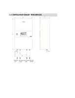
Page 5: ...3 CONFIGURATION OF THE DEVICE...

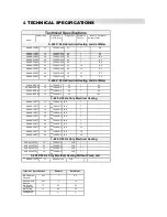
Page 6: ...700 400 2 50 26 7 10 4 3 400 V 50 Hz Only Electrical Heating UKDAX 10ETT 10 700 400 2 50 23 8 7 UKDAX 12ETT 12 700 400 2 50 23 8 7 UKDAX 16ETT 16 700 400 2 50 23 8 7 UKDAX 18ETT 18 700 400 2 50 23 8 7...

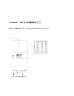
Page 7: ...Boiler installation must be done by authorized personnel 5 INSTALLATION OF BOILER...

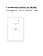
Page 8: ...Obey minimum distance that is anticipated for installation in order to reach the device for making regular maintenance 5 1 INSTALLATION CONDITIONS AND SAFETY WARNINGS...

Page 9: ...sure reduce valve installed Device installation place must be far way from blockers obstruction parts and bulges during repairing and maintenance Electric connection of the device must be made with su...

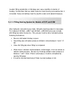
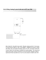
Page 10: ...r the device This process must be done byimplementing following instructions Be sure cold water inlet tap is open Open filling tap until water pressure indicator comes between 1 and 1 5 bar Close the...

Page 11: ...ng valve connected to heating system For this connection with valve must be made from cold water installation to heating system This valve must placed near place to device because of it will be used f...

Page 12: ...able which is determined according to cable length Electrical installation must have suitablespecification for cut off boiler power and residual current device that has ampere value and fuse separatel...

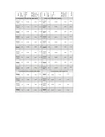
Page 13: ...3 30 4 3 40 5 4 UKDAX 20ETT 20 3 30 4 3 40 5 4 UKDAX 24EDT 24 3 36 4 3 50 5 6 UKDAX 24ETT 24 3 36 4 3 40 5 6 UKDAX 30EDT 30 3 45 5 3 63 5 10 UKDAX 30ETT 30 3 45 5 3 50 5 10 UKDAX 36EDT 36 3 54 6 3 63...

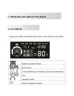
Page 14: ...he device can be follow from LCD panel Radiator operation indicator Days of week Time programming Can be made 3 pcs time programming Hour Capacity indicator Ready to Operation indicator 6 OPERATION AN...

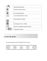
Page 15: ...icator Over Heating Indicator Over Heating Difference Value Pump operation indicator Freezing prevention indicator Room ThermostatConnection indicator Temperature indictor Use knobs located under LCD...

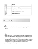
Page 16: ...n be occur associated with intervention to device by unauthorized people Before operating the device suitability of all connections of mechanics and electrical must be controlled Heating system must h...

Page 17: ...er cables Be sure that cables were connected to correct places Loosen cable connections can be caused accidents Open residual current device the fuse After all indicating lights are seen within a few...

Page 18: ...ress button minute blinks minute setting between 0 and 60 is done by pressing or buttons 5 By pressing button or not pressing any button for a 10 second exit from setting menu by saving settings While...

Page 19: ...summer mode setting can be made by or buttons while standby mode or operation mode 3 After the device is only taken to hot water heating mode summer mode setting can be made For this after it is press...

Page 20: ...starting up by authorized service room thermostat connection will be activated from inside of device After room thermostat connection is done to the device it is needed to room thermostat bring into...

Page 21: ...ange heating mode by user by consciously or by mistake For radiator heating modes if users want they can persuade operating of device maximum 55oC by changing into heating mode to ground heating mode...

Page 22: ...with 3 different operation modes 1 Only Radiator Heating Mode Device only makes heating Although tap water is wanted to heat heating tap water cannot be occurred while heating mode is active 2 Only Ta...

Page 23: ...uring program time and temperature difference can be made If the program is made or the program is active position device stays in heating mode for period of times that are not programmed With button...

Page 24: ...program finish minute is determined 9 Press to button temperature indicator blinks With or chosen program operation temperature is determined 10 Press button is seen Temperature setting indicator bli...

Page 25: ...ringing the water temperature to security level 35O C During Anti frost cycle is seen at LCD Anti Blockade Function Pump and 3 way valve inside the device start to operate once every 18 hrs If you do...

Page 26: ...7 ELECTRICAL DIAGRAM...

Page 27: ...between 1 2 bars 2 Call authorized service E1 Heating sensor damage Although you wait for a while if you have still seen the same code call the authorized service E3 Warning of water temperature is o...

Page 28: ...tions 1 Connections must be made again 2 Sealing gasket must be renew 2 Sealing gasket is damaged X Keypad or PCB damage X Call the authorized service 1 Unproper cable using Turn off the device call t...

Reviews: