57
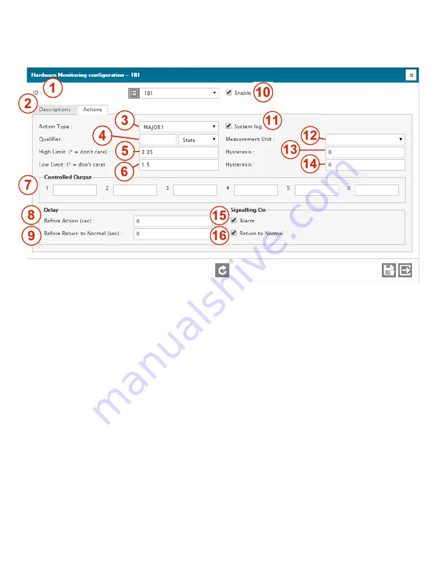
Typical configuration screen of a hardware monitoring input.
1 –
ID
ID of the selected input. Select from the drop-down menu (1B1 in this case).
2 –
I/O DESCRIPTION RETRIEVAL
Click to retrieve and display the current normal description of that ID. Normally hidden to minimize data transfers
on low speed or high fee data connections.
3 –
ACTION TYPE
Selects the action type that will happen when an out-of-limit condition occurs. 3 types are available: Major alarm,
Minor alarm, and Command (CMD). On CMD, no alarm will be triggered. Use this Action when you want to take
actions without triggering any alarms.
4 –
QUALIFIER AND QUALIFIER STATE - DATA
Qualifying element (operand) which can be any input, output, flag, timer, SNMP GET, Logic Gate, etc. Essentially
any ID in the Cortex can be used to mute or unmute the input to prevent it from taking any action. When the Qualifier
is active, the input will be monitored and be able to generate alarms. When the qualifier is non-active (or normal),
the input will be muted and it will not be able to generate an alarm. To invert the Qualifier’s level, simply put a ! in
front of its ID. For example, use !1D01 to invert it. Leave the Qualifier field blank for a “don’t care” condition.
STATE
(default setting): the State (Normal or Active) of the input being qualified can change only when the Qualifier
is active. Readings from the input (Current Value) continue to be updated periodically independently from the
Qualifier state.
DATA
: Same as the STATE mode, but in this case the readings from the input (Current Value) remain frozen at
their latest values, as long as the Qualifier is not active. This mode is used like a “Sample-and-Hold” for the readings
from the input.
5 –
HIGH LIMIT
Voltage value above which the input state will switch from normal to active. Factory-set but changeable by user.
6 –
LOW LIMIT
Voltage value below which the input state will switch from normal to active. Factory-set but changeable by user.
7 –
CONTROLLED OUTPUT
Summary of Contents for Cortex Series
Page 2: ...2...
Page 5: ...5...
Page 9: ...9 1 3 Specifications...
Page 18: ...18 2 4 2 Jumpers for the Cortex 320 Jumpers and switches location on the Cortex 320 main board...
Page 91: ...91...


