113
Cortex 320
Setup
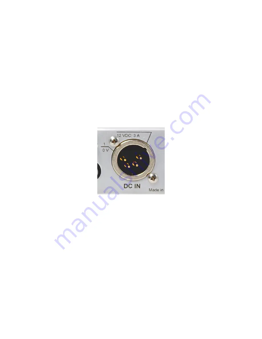
Connecting the unit to a power supply
The Cortex 320 power rating is 12 VDC @ 3 Amps, but it can run on any DC voltage
between 10 and 15 volts. The actual current consumption depends on the actual
supply voltage. A 4-pin XLR connector is used for the power supply: male on the
Cortex 320 and female on the power supply side.
If you did not purchase your power supply unit from Davicom, you will want to make
your own supply cable with the XLR pigtail supplied with your Cortex unit. The
pinout is indicated directly on the back panel.
Summary of Contents for Cortex 360
Page 15: ...15 2 Go to IP Configurations...
Page 17: ...17 4 IP ADDRESS Set the IP address of the unit 5 NETMASK Set the Netmask of the unit...
Page 19: ...19 8 SAVE Save the screen content 9 EXIT Exit menu...
Page 20: ...20 Configuring the Cortex 360 IP Parameters E mail tab 1 Go to the E mail tab...
Page 27: ...27 Configuring Users Go to the Users menu...
Page 33: ...33 Configuring Site ID Go to Site ID...
Page 35: ...35 4 SAVE Save the screen content 5 EXIT Exit menu...
Page 36: ...36 Configuring Date Time and Location 1 Go to Time Date and Location...
Page 40: ...40 7 SYNC NOW Perform a manual clock synchronization 8 SAVE Save the screen content...
Page 42: ...42 Configuring Alarm Call Lists 1 Go to Alarm Call Lists...
Page 55: ...55 Configuring Alarm Parameters Go to Alarm Parameters...
Page 58: ...58 1 Go to the Inputs menu 2 Go to AC Power Fail...
Page 62: ...62 10 Save the configuration 11 Exit the configuration screen...
Page 67: ...67 6 Your setup should look like this You are now ready to move on to the configuration step...
Page 68: ...68 Configuring Metering Inputs 1 Go to the Inputs menu 2 Go to Metering Inputs...
Page 71: ...71 6 Go to the Actions tab 7 Set the Voltage Range to 2 5...
Page 72: ...72 8 Set the desired Measurement Unit Fahrenheit Celsius For this example we will be using F...
Page 75: ...75 11 Set the Low and High Limits These limits determine when the alarm will go off...
Page 77: ...77 13 Save the configuration 14 Exit the configuration window...
Page 81: ...81 4 Your setup should look like this You are now ready to move on to the configuration step...
Page 86: ...86 8 Save the configuration 9 Exit the configuration screen...
Page 91: ...91 6 Your setup should look like this You are now ready to move on to the configuration step...
Page 103: ...103 3 In the System Status tab select the Log Transfer Type 4 Select the Callout Device...
Page 105: ...105 7 Set the Number of attempts 8 Set the Delay between attempts in minutes...
Page 107: ...107 11 Go to the System Log tab 12 Select the Log Transfer Type...
Page 108: ...108 13 Select the Callout Device 14 Set the Transfer Time...
Page 109: ...109 15 Set how often the transfer will occur 16 Set the Number of attempts...
Page 112: ...112 21 Exit the configuration screen...
Page 124: ...124 2 Go to IP Configurations...
Page 126: ...126 4 IP ADDRESS Set the IP address of the unit 5 NETMASK Set the Netmask of the unit...
Page 128: ...128 8 SAVE Save the screen content 9 EXIT Exit menu...
Page 129: ...129 Configuring the Cortex 320 IP Parameters E mail tab 1 Go to the E mail tab...
Page 136: ...136 Configuring Users Go to the Users menu...
Page 142: ...142 Configuring Site ID Go to Site ID...
Page 144: ...144 4 SAVE Save the screen content 5 EXIT Exit menu...
Page 145: ...145 Configuring Date Time and Location 1 Go to Time Date and Location...
Page 150: ...150 7 SYNC NOW Perform a manual clock synchronization 8 SAVE Save the screen content...
Page 152: ...152 Configuring Alarm Call Lists 1 Go to Alarm Call Lists...
Page 165: ...165 Configuring Alarm Parameters Go to Alarm Parameters...
Page 168: ...168 1 Go to the Inputs menu 2 Go to AC Power Fail...
Page 172: ...172 10 Save the configuration 11 Exit the configuration screen...
Page 178: ...178 Configuring Metering Inputs 1 Go to the Inputs menu 2 Go to Metering Inputs...
Page 181: ...181 7 Set the desired Measurement Unit Fahrenheit Celsius For this example we will be using F...
Page 184: ...184 10 Set the Low and High Limits These limits determine when the alarm will go off...
Page 186: ...186 12 Save the configuration...
Page 187: ...187 13 Exit the configuration window...
Page 191: ...191 4 Your setup should look like this You are now ready to move on to the configuration step...
Page 201: ...201 6 Your setup should look like this You are now ready to move on to the configuration step...
Page 213: ...213 3 In the System Status tab select the Log Transfer Type 4 Select the Callout Device...
Page 215: ...215 7 Set the Number of attempts 8 Set the Delay between attempts in minutes...
Page 217: ...217 11 Go to the System Log tab 12 Select the Log Transfer Type...
Page 218: ...218 13 Select the Callout Device 14 Set the Transfer Time...
Page 219: ...219 15 Set how often the transfer will occur 16 Set the Number of attempts...


