background image

10

3.2.5 Mounting description of the Tube on the Injection Valve

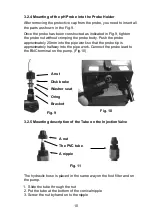
Fig. 10

A nut
Disk brake
Washer seat
Oring
Bracket

A nut
The PVC tube
A nipple

3.2.4 Mounting of the pH Probe into the Probe Holder

After removing the protective cap from the probe, you need to insert all 
the parts as shown in the Fig.9.

Once the probe has been constructed as indicated in Fig.9, tighten 
the probe nut without crimping the probe body. Push the probe 
approximately 20mm into the pipe work so that the probe tip is 
approximately halfway into the pipe work. Connect the probe lead to 
the BNC terminal on the pump. (Fig.10)

The hydraulic hose is placed in the same way on the foot filter and on 
the pump.

  1.  Slide the tube through the nut 

2. Put the tube at the bottom of the conical nipple 
3. Screw the nut by hand onto the nipple

Fig. 9

Fig. 11

Summary of Contents for AS Series

Page 1: ...e serious bodily injury and or property damage The installation of this product should be carried out by a person knowledgable in swimming pool plumbing requirements following the installation instruc...

Page 2: ...lamp 9 3 2 3 Mounting of Injection Valve 9 3 2 4 Mounting of the Probe on the Probe Holder 10 3 2 5 Mounting description of Tube on the Injection Valve 10 4 Commissioning and Operation 11 4 1 Calibrat...

Page 3: ...se for which it has been expressly designed namely the dosing of liquids Any different use is to be considered dangerous The pump should not therefore be used for applications that were not allowed fo...

Page 4: ...power supply Before carrying out any service on the pump 1 Disconnect the mains power from the unit and 2 Relieve all the pressure from the pump head or the injection tube In the event of possible los...

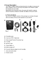
Page 5: ...duct needed to maintain the balance of the pool water 2 1 Parts description Here are the complete contents of the package you received All parts will be necessary for the proper operation of your devi...

Page 6: ...set point 2 Press CAL allows calibration of the pH level associated to the SET button to change the value of the set point 3 Value level of pH in water 4 pH unit of measure to determine pool water ch...

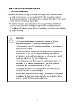
Page 7: ...f 200mm between the probe C and the injection valve E The injection valve E must be placed last in the pipework hydraulic installation In the case of an installation with redox and pH regulation it is...

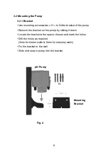
Page 8: ...the pump Remove the bracket on the pump by sliding it down Locate the bracket in the space chosen and mark the holes Drill the holes as required 3mm for timber walls 6mm for masonry walls Fix the bra...

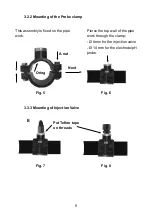
Page 9: ...ng of Injection Valve Fig 5 Fig 7 Fig 6 Fig 8 Oring A nut Put Teflon tape on threads Next Pierce the top wall of the pipe work through the clamp 8mm for the injection valve 14 mm for the electrode pH...

Page 10: ...the probe has been constructed as indicated in Fig 9 tighten the probe nut without crimping the probe body Push the probe approximately 20mm into the pipe work so that the probe tip is approximately h...

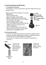
Page 11: ...t for reuse at the time of winterising 2 Rinse the probe in tap water for at least 20 minutes Steps Before carrying out the calibration of the probe remember to Stop the filtration pump Close the isol...

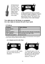
Page 12: ...leted It is now ready to measure the pH of your pool 3 Next immerse the probe in the pH 7 solution stir around in bottle and leave it in the solution being careful not to touch the probe or the cable...

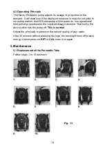
Page 13: ...ational time period proportional to the required dosage demand That is why the device often has the pump off This is normal Adjust the pH slowly to preserve the natural quality of your water After 30...

Page 14: ...5 3 Controller Wintering Only in areas where subzero temperatures are experienced During winterising you must protect the peristaltic tube It is advisable to remove the peristaltic tube and flush it...

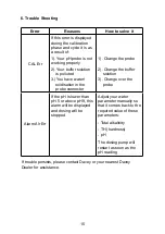
Page 15: ...nnector 1 Change the probe 2 Change the buffer solution 3 Change over the probe Alarm Alr Err If the pH is lower than pH 5 or above pH 9 this alarm will be displayed and dosing will be stopped Adjust...

Page 16: ...m misuse or negligent handling improper use for which the product was not designed or advertised failure to properly follow the provided installation and operating instructions failure to carry out ma...

Reviews: