Operation
PSM-500/500L/500LT SCPC Satellite Modem
Page 3-34
PSM-500/500L/500LT - Rev. 0.91
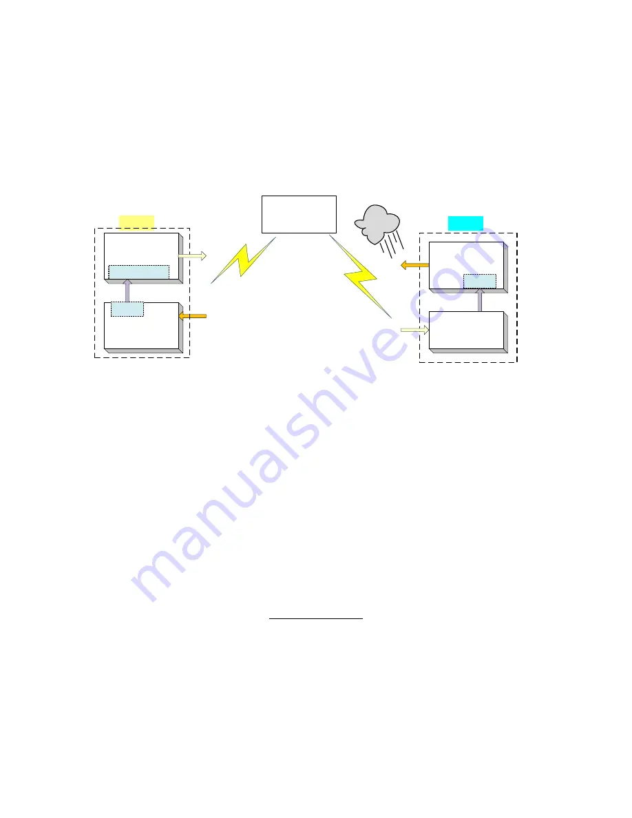
Eb/No on the front panel of 7.5 dB, and is currently outputting –15 dBm. Next it begins raining at
location “B”, and the Eb/No drops to –7.0 then –6.8 dB. Modem “B” is constantly sending update
messages to “A” and reports the current Eb/No. When “A” sees the drop in Eb/No, it slowly
begins to raise the output power, and raises it again when it sees further drops. As the rain
increases in intensity, and the Eb/No decreases again, “A” continues to increase its power level
to compensate, and when the rain diminishes and quits, it also lowers its power level to
compensate. The operation is therefore a feedback control loop with the added complication of a
significant time delay.
Satellite
Site A
Site B
Modem A
Modulator
Modem A
Demodulator
Modem B
Modulator
Modem B
Demodulator
Mux
Mux
Eb/No
Eb/No
AUPC Control
Figure 3-4 AUPC
There must be safeguards built into the AUPC system. First, the Modulator has two additional
parameters which allow control of the maximum and minimum power output level. The other
controls are built into the operating control software to limit response times and detect adverse
operating conditions.
3.8.1 AUPC Setup Guide
The normal method for setting up AUPC over a point to point link is to use the PSM-500's built in
multiplexer to provide the necessary communications channel. Since AUPC can be enabled in a
single direction the multiplexer must be enabled in only the direction necessary to return Eb/No
information to the controlled transmit modem. The best way to illustrate this is with an expansion
of the example shown above for sites A and B. Here are the steps assuming that we start with a
working link between A and B without any multiplexers or AUPC enabled. We will also assume
that the desired receive Eb/No that we wish to maintain at site B is 7.0 dB.:
Site B AUPC Setup
1. Set the B Modulator Multiplexer to Custom mode. Note this kills the link from B to A until
the A Demod is set with the same Multiplexer settings.
2. If not using the ESC channel for some other reason then set the ESC Overhead to
“Disabled”.
3. Set the MCC Overhead Rate to 1200 bps. This carries the AUPC information and 300
baud is the absolute minimum required. But in most cases you should start at this higher
rate. You can always go back and try lower values. The speed here determines the time
it takes to send the information.


