


ADIO WIRELESS BRIDGE USER’S MANAUL REV. 02
12
Digital Signal Bridge
This is similar to the analog signal bridge except that the outputs will transition when the inputs cross
logic voltage thresholds. The High input voltage threshold is 2.1V and the low threshold is 0.8V. By
default the high output voltage is 3.3V but this can be adjusted with the
chX.lvl.
dovolts command. See
the ADIO command reference table for details. For digital I/O line passing the following setup should
occur. Optional parameters are noted.
Input radio:
1.
Set the ch.X.type to 3
2.
Set the ch.X.token value
3.
Optional: Set ch.chX.cd if you want the radio to transmit only on an input signal change. Also set
cd.rate if this parameter is used.
4.
Set the io.txrate parameter if change detect is not used
5.
Optional: Use set store to save settings to non-volatile memory.
Output radio:
1.
Set the ch.X.type to 4
2.
Set the ch.X.token value
3.
Set the pkts.en command to 1.
4.
Optional: set default starting voltage, timeout and output voltage level if desired.
5.
Optional: Use set store to save settings to non-volatile memory.
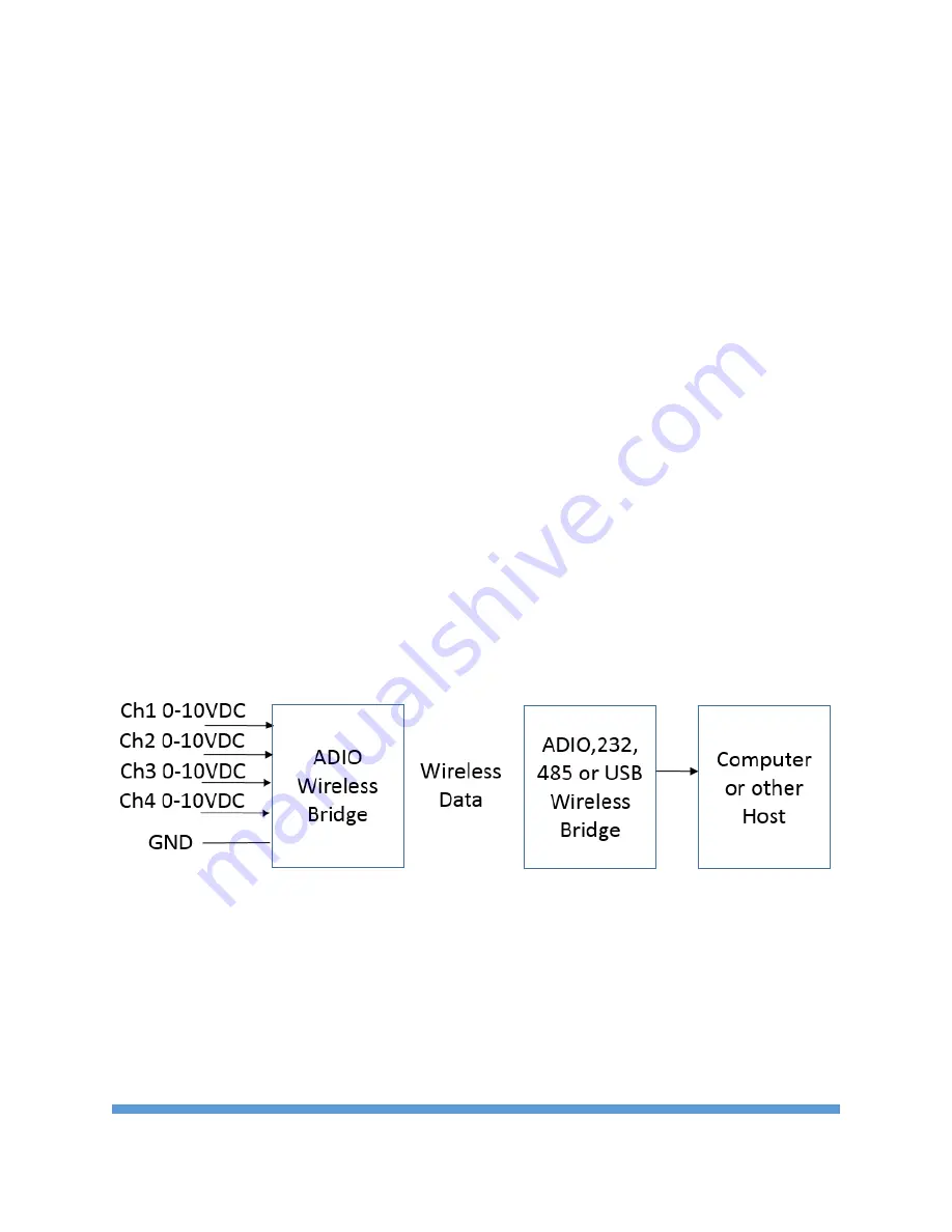
Wireless Data Collector
Fig. 8 Wireless Analog Data Collector
The other Datawave Wireless Bridge products can receive and process data from the ADIO Wireless
Bridge. Figure 8 shows the typical architecture for this scenario. The ADIO Wireless Bridge can transmit
the status of the Input channels at an interval specified by the io.txrate command. With the pkts.en
command set to 1, the receiving radios output the data in JSON (default) or simple text format. Figure 9
shows an example output packet. In Figure 9, the name field is blank and all the channels of the
transmitting radio are set to analog inputs (AIN). The voltage value of each channel is shown in
millivolts.