background image


22 

Comparing colour saturation among cameras 


i. 

Aiming the camera at Chroma Du Monde (Set camera to AUTO). 

 
ii. 

Select  VECTORSCOPE  mode  on  the  VS-100  using  the  NEXT 
MODE option. 

 
iii. 

The  VECTORSCOPE  matrix  displaying  on  VS-100  represents  the 
colour components from the camera. 

 
iv. 

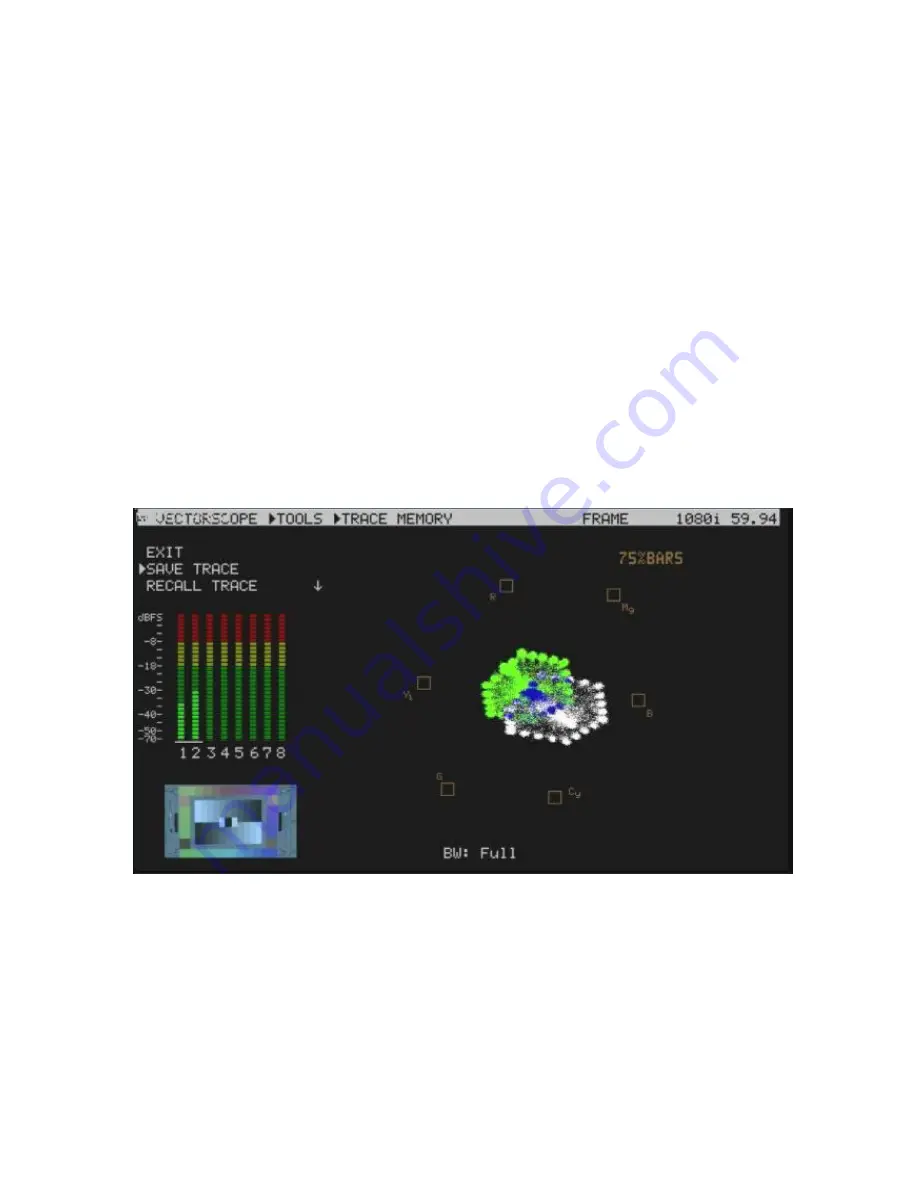
Use the SAVE TRACE feature under TOOLS to compare the colour 
components between cameras. 


v. 

The  matrix  indicates  the  current  colour  components  of  the  camera 
by  showing  the  positioning  of  the  dots.  When  two  cameras  have 
aligned luminance, the larger the VECTORSCOPE matrix, the more 
colour saturation it represents. 


Summary of Contents for VS-100

Page 1: ...Sampling Video Scope VS 100 Instruction Manual www datavideo tek com...

Page 2: ...r Panels 9 VS 100 Output Display 10 Menu Control and Options 11 NEXT MODE 11 VIDEO DISPLAY 11 TOOLS 12 TRACE MEMORY 12 SET BANDWIDTH VECTORSCOPE TOOLS 12 SET UP BARS VECTORSCOPE TOOLS 12 SET RGB YCbCr...

Page 3: ...o Technologies will try to give correct complete and suitable information However Datavideo Technologies cannot exclude that some information in this manual from time to time may not be correct or may...

Page 4: ...at the total of the ampere ratings on the products plugged into the extension cord do not exceed the extension cord s rating 10 Make sure that the total amperes of all the units that are plugged into...

Page 5: ...ree one year extension to the standard Warranty providing the product is registered with Datavideo within 30 days of purchase For information on how to register please visit www datavideo tek com or c...

Page 6: ...rocess easier and more efficient Datavideo presents the VS 100 a cost effective Sampling Video Scope This unit provides quick accurate and standardized ways to calibrate and align signals from cameras...

Page 7: ...ith menu based volume control Save and Recall trace menu options for quick and easy overlay comparison of video traces Parade Display can be toggled between RGB and YCbCr Vectorscope can be toggled be...

Page 8: ...8 Example Set Up...

Page 9: ...Rear Panels 1 Menu dial and push to select button 2 3 5mm jack socket for audio monitoring 3 Power ON OFF switch with LED 4 DC 12V 0 2 A 4W input connector 5 HDMI output 6 SDI HD SDI output clean loo...

Page 10: ...10 VS 100 Output Display...

Page 11: ...r menu select EXIT from the current options list The Main Menu options are TOOLS NEXT MODE VIDEO DISPLAY AUDIO VOLUME AUDIO CHANNEL CONFIGURATION NEXT MODE When first switched on the VS 100 will displ...

Page 12: ...le points are displayed in blue In this way two sources can be compared or a single source can be checked to see if its output drifts during extended use SET BANDWIDTH VECTORSCOPE TOOLS This option ca...

Page 13: ...right across the waveform In this way the rest of the waveform can be viewed at the same level of detail X DELAY WAVEFORM TOOLS This feature allows the waveform display to be panned right or left at t...

Page 14: ...power on NOTE This setting can be over ridden by the VIDEO DISPLAY setting in the VS 100 main menu CAPTURE The VS 100 scope displays can be set to sample FIELD1 FIELD2 or FRAME depending on the users...

Page 15: ...e background or reference white card 5 If necessary adjust R Red or B Blue GAIN of the camera to move the shown sample points for white video into the center graticule box of the VS 100 Vectorscope Co...

Page 16: ...if the pattern is distributed towards the right 100 it can mean the camera is over exposed If the pattern is distributed towards the left 0 it can mean the camera is under exposed 5 If there are readi...

Page 17: ...ed in line with the grayscale chart However if the matrix is not evenly distributed it means that the Gamma is not correctly set and will lead to further adjustment of the camera 5 Once the first came...

Page 18: ...ra to standardised colour levels such as R 650mv G 600mv B 600mv These adopted set reference points can then ensure image consistency in future production runs and any post production grading 5 Once t...

Page 19: ...mode on the VS 100 using the NEXT MODE option 3 Now the VECTORSCOPE displays the analyzed colour components If the white balance of one camera had been altered the VECTORSCOPE matrix can be used as a...

Page 20: ...to one another in a straight line iii When White balance is not correctly adjusted the PARADE will show unbalanced trace iv When the lighting is not evenly spread out the PARADE will show traces which...

Page 21: ...or cap the lens ii Select PARADE mode on the VS 100 using the NEXT MODE option iii The noise value will be displayed on the chart The thicker the value on the line chart the greater the noise level T...

Page 22: ...matrix displaying on VS 100 represents the colour components from the camera iv Use the SAVE TRACE feature under TOOLS to compare the colour components between cameras v The matrix indicates the curr...

Page 23: ...8 Impedance 75 Return Loss HD 15 dB 5 MHz to 750 MHz 10 dB 750 MHz to 1 5 GHz SD 15 dB 5 MHz to 270 MHz Equalization 200 m Belden 8281 cable at 270 Mbps 100 m typical of Belden 1694A at 1 485 Gbps HDM...

Page 24: ...el 44 1457 851 000 Fax 44 1457 850 964 E Mail sales datavideo co uk Datavideo Technologies Co Ltd Tel 886 2 8227 2888 Fax 886 2 8227 2777 E mail service datavideo com tw Datavideo Technologies China C...

Reviews: