background image


35 


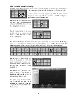
DVE Crop 

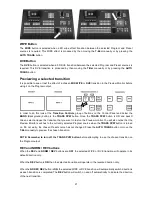
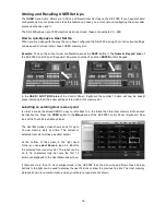
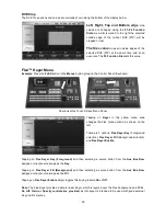
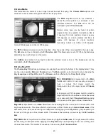
The DVE Crop options and values are currently shown along the bottom of the display below.  


Left, Right, Top and Bottom edge

  crop 

values are changed using the 

F1~F4  Function 

Dials.

 As a dial is turned to the right the selected 

outside  edge of the current DVE (PIP) will be 

cropped or lost. 


The Size value

  crops all outside edges of the 

selected DVE  (PIP) at the same time and at an 

even rate. The 

F5 Function Dial

 sets this value. 


Flex™ Keyer Menu 

Example:

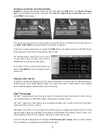
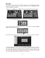
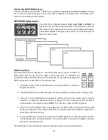
 Press the 

FLEX

 button in the 

Menus

 button group on the Control Panel / Keyboard. 

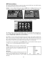
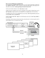
Now look at the Touch Screen Menu Panel. 


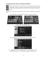
Tapping on 

Keyer

  in the yellow menu area 

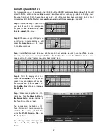
changes the Flex  menu options,  as shown on the 

left.  


There are 3 options, 

Flex Keyer Key 

(Foreground 

selection),

  Flex Keyer Fill 

(Background  selection) 

and 

Flex Keyer Enable


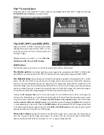
Tapping on 

Flex Keyer Key (Foreground)

  and then selecting a source button from the 

Aux Bus Row


assigns an input source image as the 

Key


Tapping on 

Flex Keyer Fill (Background)

  and then selecting a source button from the 

Aux Bus Row


assigns an input source image as the 

Fill


Tapping on 

Flex Keyer Enable

 simply toggles this keying feature 

On

 or 

Off


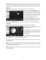
Note:

 The Flex Keyer provides a simple linear Keyer, which is layered over the Flex background and DVEs. 

No Lift, Gain, or Opacity controls are provided

, as this keyer is intended to be used with good external 

Key and Fill sources.  


Summary of Contents for SE-3000

Page 1: ...8 16 CHANNEL SWITCHER SE 3000 Instruction Manual www datavideo tek com...

Page 2: ...ions 14 SDI Video Inputs 14 Setting the Resolution of the SE 3000 14 DVI Input Input 8 15 Input Channels 9 16 15 Video Outputs 16 Auxiliary HD SDI Outputs 1 4 16 How to assign Auxiliary Output sources...

Page 3: ...rans 25 DSK Trans 25 FTB Trans 25 Freeze Menu 26 Freeze On Off 26 Mode 26 Stills Menu 27 Grabbing Saving a Still to memory 27 Loading an existing Still from memory 28 Deleting a saved Still from memor...

Page 4: ...ee Chip Camera 37 Do not mix SD and HD standards when keying 37 White Balance the Camera 37 Lighting 38 Control Panel Button Groups used 38 Chroma Key Quick Set Up 39 Chroma Matte 40 Chroma Key Ctrl 4...

Page 5: ...58 Disclaimer of Product and Services The information offered in this instruction manual is intended as a guide only At all times Datavideo Technologies will try to give correct complete and suitable...

Page 6: ...hat the total of the ampere ratings on the products plugged into the extension cord do not exceed the extension cord rating 10 Make sure that the total amperes of all the units that are plugged into a...

Page 7: ...or contact your local Datavideo office or authorized Distributors Certain parts with limited lifetime expectancy such as LCD Panels DVD Drives Hard Drives are only covered for the first 10 000 hours...

Page 8: ...BNC and Component Y Pb Pr Normal mixer features such as Picture in Picture PiP as well as Cut Wipe and Mix dissolve transitions are available On top of these the SE 3000 can perform advanced Digital...

Page 9: ...m PGM Preview PVW Program DSK Preview DSK outputs available HD Component and down converted SD Component output as well as HD SDI output 4 user delegated auxiliary HD SDI outputs Store up to 100 still...

Page 10: ...panel of the SE 3000 Main Unit has a ventilation plate to prevent overheating please ensure that adequate airflow is provided The Main Unit also comes with 19 rack mounts already fitted Rear Panel Co...

Page 11: ...Preview of input sources with PGM PVW Still Store 1 and 2 see page 17 REF IN REF LOOP Use these connections to loop external house sync through the SE 3000 Mixer See page 50 SD COMPONENT OUTPUT Downsc...

Page 12: ...ector See page 51 for more information RS 422 IN RS 422 OUT 9 Pin D Sub connector See page 54 for more information RS 232 9 Pin D Sub connector See page 53 for more information GPI 15 Pin D Sub connec...

Page 13: ...n with the mixer The default IP address for the Control Panel is 192 168 1 115 and the Main unit is 192 168 1 114 Both units can communicate with each other across an existing DHCP network but the IP...

Page 14: ...with the exception of input 8 See DVI Input Input 8 on the following page Setting the Resolution of the SE 3000 The SE 3000 has six standard HD resolution settings To set the mixer s resolution press...

Page 15: ...void using sources with HDCP protected video Input Channels 9 16 NOTE Units with only 8 inputs can be upgraded to 16 inputs please speak with your local Datavideo supplier for upgrade availability and...

Page 16: ...area of the Control Panel Keyboard Then tap on Analog Out and choose one of the six options above This Analogue output has a further setting for YPbPr or RGB output depending on your connected equipm...

Page 17: ...the Multi 1 Multi 2 outputs see page 11 then two Datavideo TLM 170H monitors could be used Alternatively you could use two Datavideo DAC 8 converters to change HD SDI signals to HDMI and then feed th...

Page 18: ...Screens 1 4 here is the same for the other MultiViewer set ups When you look at the initial layout of Dual Mode 2 above you can see that the top two images in both screens are Preview Program for the...

Page 19: ...button in the Menus button group of the Control Panel Keyboard Now look at the Touch Screen Menu Panel and tap on the number 1 The Touch Screen will change and in the bottom right hand corner there is...

Page 20: ...acklit Green on this row When transitioning between sources using the T Bar the selected Preset Next source button will change from Green to Yellow Transitions Group The Transitions group of buttons a...

Page 21: ...he TRANS PVW button is ON and backlit Green select and use the transition that you want to test on the Preview monitor You will also notice that the Preview Monitor switches to the currently selected...

Page 22: ...ue and white White represents the current Program image and Blue represents the Preset Next source image The shape and edges of these White and Blue areas within each Icon gives an idea of what the se...

Page 23: ...ttom of the display below The Wipe Border Menu allows control of the Wipe Border Matte Colour Palette The Colour Palette allows selection of a colour for the Wipe Border Matte Tap on the Colour Palett...

Page 24: ...creen Shade Soft This blurs or softens the boundary line B between the Wipe Shade Matte area 1 and the Wipe Border Matte area 2 Shade Position The position of the boundary line B between the two matte...

Page 25: ...test the effect of a chosen DVE transition in the Preview Monitor before using it on the Program output See Previewing a selected transition on page 21 Transition Selection To select a DVE transition...

Page 26: ...Menus button group of the SE 3000 Control Panel Keyboard Now look at the Touch Screen Menu Panel When the Freeze Menu is selected Icons for all 16 input sources are shown Tap or select the input you...

Page 27: ...ook at the Touch Screen Menu Panel Grabbing Saving a Still to memory The Grab Save option allows new Still Images to be created by grabbing saving the current Program video frame image to one of the t...

Page 28: ...ail picture or select it by entering the Stills number and then tapping the Load Still option The selected still will be loaded into the currently highlighted stills buffer In the above example still...

Page 29: ...ch is also confirmed under the RGB values on the right Hue Sat and Luma values The colour of the Bus Matte can also be controlled by adjusting the Hue Sat and Luma values These three values can be fin...

Page 30: ...backlit green indicating that it has user settings stored within this memory slot Labelling an existing User memory slot In order to make the stored USER 1 easy to refer back to in the future then thi...

Page 31: ...Set Up To Delete an existing User Memory slot or Set Up select the Memory position using the Touch Screen Menu Panel Then tap on the Delete Memory option in the Yellow menu area Confirm deletion of t...

Page 32: ...r as a Flex preview screen so you can prepare your chosen Flex layout before displaying it on the preview or program outputs See How to assign Auxiliary Output sources on page 16 Saving the Flex set u...

Page 33: ...DVE PIP image Over the top of the smaller DVE PIP box is an arrow which shows which way this image has been rotated The arrow indicates the normal top edge of the DVE PIP image If the arrow is pointin...

Page 34: ...blur and soften the outside edge of the selected DVE PIP or border DVE Border The DVE Border options and values are currently shown along the bottom of the display below Hue Sat and Luma values define...

Page 35: ...apping on Keyer in the yellow menu area changes the Flex menu options as shown on the left There are 3 options Flex Keyer Key Foreground selection Flex Keyer Fill Background selection and Flex Keyer E...

Page 36: ...ignal from the Decklink card is then fed to input 15 on the SE 3000 see diagram below Tap on Flex Keyer Key Foreground and then select button 15 from the Aux Bus row on the Control Panel If the Fill s...

Page 37: ...It is best to avoid trying to use standard definition SDI green or blue screen footage with a HD background because the keying edges in the SD image will become fuzzy during the SD to HD upscaling pr...

Page 38: ...g on the subject will obviously vary according to the effect that you are looking for and as long as the backdrop is evenly lit this should not be a problem Control Panel Button Groups used To Chroma...

Page 39: ...e Chroma button in the Keyer Controls button group Step 3 Select the foreground video source to be keyed In our example we want to use a green screen source connected to Input 10 So we would press but...

Page 40: ...bottom of the display below There are two colour palettes Main and Chroma shown The Main palette can be referred to when changing the Key Acceptance and Key Lift values The Chroma palette is affected...

Page 41: ...hroma Acceptance Angle are suppressed to mono i e they have their Chroma removed Usually starting with a value of 50 should produce reasonable results This value can then be fine tuned up or down usin...

Page 42: ...the Keyer Controls button group Step 3 Select the foreground video source to be keyed In our example we want to use the STILL 1 source to overlay some text So we would press STILL on the Aux Bus Row...

Page 43: ...of Opacity will make the overall key image less transparent Luma Key Invert This setting reverses the effect the current Luma Key settings So if you can currently see the background video through the...

Page 44: ...ction can then be switched on by pressing the MASK button in the Keyer Controls button group Now look at the Touch Screen Menu Panel The Mask Menu options are shown at the bottom of the display The F2...

Page 45: ...ues on the right The Hue adjustment moves the crosshair around the colour palette in a clockwise or anti clockwise direction The Hue value angle can be controlled by the F1 Function dial Certain colou...

Page 46: ...d When on back lit Green this button includes the background image video in any chosen transition from Preview to Program When this button is toggled or switched off any Keyer transition chosen will n...

Page 47: ...ansition in the Preview Monitor before using it on the Program output In order to do this look at the Transition Controls group of buttons on the Control Panel and below the BGND Background button is...

Page 48: ...Keyer Controls button group Step 3 Select the foreground video source to be keyed In our example we want to use the CG 350 input source on 15 to overlay some text So we would press button 15 on the A...

Page 49: ...y set up as described on the previous page 1 If the DSK1 button is Off and the LED above it is Red then DSK1 is not active in Program or Preview 2 If the DSK1 button is On and the LED above it is Red...

Page 50: ...on the rear of the Main unit Once the BNC connections have been made and the external reference is supplied follow the instructions below Press the SETUP button in the Menus button group on the Contr...

Page 51: ...LED 1 Pin 4 Pin 2 2 Pin 8 Pin 6 3 Pin 12 Pin 10 4 Pin 16 Pin 14 5 Pin 20 Pin 18 6 Pin 24 Pin 22 7 Pin 28 Pin 26 8 Pin 32 Pin 30 9 Pin 31 Pin 34 10 Pin 27 Pin 29 11 Pin 23 Pin 25 12 Pin 19 Pin 21 13 Pi...

Page 52: ...B Pin 8 7 SE 3000 Pin 28 Unit 1 Tally B Pin 11 SE 3000 Pin 26 Unit 1 Tally B Pin 13 8 SE 3000 Pin 32 Unit 1 Tally B Pin 5 SE 3000 Pin 30 Unit 1 Tally B Pin 15 9 SE 3000 Pin 31 Unit 2 Tally A Pin 1 SE...

Page 53: ...tive within the current version of firmware Please check with your local Datavideo Office for firmware updates and a PDF copy of the latest manual PIN1 GPI IN 1 PIN3 GPI IN 2 PIN5 GPI IN 3 PIN7 GPI IN...

Page 54: ...it Z TX 3 Receive A RX 4 5 6 7 Transmit Y TX 8 Receive B RX 9 Ground Speed 9600bps 8 Bits 1 stop bit RS 422 OUT This connector has no function as yet The SE 3000 features a 9pin D Sub RS 422 OUT port...

Page 55: ...ed se3000_PU_usb_startup 3 Copy these 4 items and their contents into a new folder on the empty USB pen drive called se3000 4 Switch OFF the SE 3000 in the normal way and remove the front ventilation...

Page 56: ...thin the Menus area of the Control Panel Keyboard Then look at the Touch Screen Menu Panel which should display the information required Please check with your local Datavideo office if you feel that...

Page 57: ...Hz to 750 MHz 10dB 750 MHz to 1 5 GHz SD 15dB 5 MHz to 270 MHz Equalization 265 m Belden 8281 cable at 270 Mbps 135 m typical of Belden 1694A at 1 485 Gbps Operating temp 0 C to 40 C Humidity 10 to 90...

Page 58: ...31 30 261 96 56 Fax 31 30 261 96 57 E Mail service datavideo nl Datavideo UK Limited Tel 44 1457 851 000 Fax 44 1457 850 964 E Mail sales datavideo co uk Datavideo Technologies Co Ltd Tel 886 2 8227 2...

Reviews: