
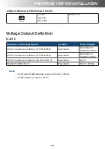
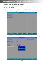
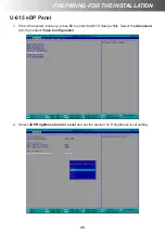


42
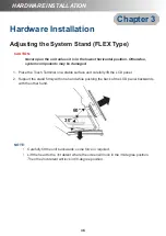
HARDWARE INSTALLATION
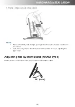
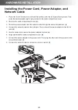
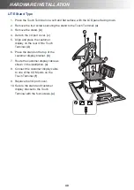
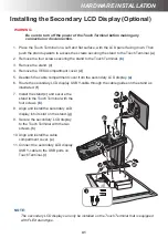
HARDWARE INSTALLATION
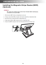
Installing the Magnetic Stripe Reader (MSR)
(Optional)
WARNING:
Be sure to turn off the power of the Touch Terminal before making any
connection or disconnection.
1. Remove the MSR module compartment cover.
(a)
2. Firmly connect the MSR connector into the slot inside the compartment.
(b)
3. Remove the two screws from the compartment.
(c)
4. Align and install the MSR module onto its compartment.
(d)
5. Secure the MSR module to the Touch Terminal with the two screws.
(e)
a
e
c
b
d
Summary of Contents for H-610
Page 1: ...HiFive Series Version 2 0 User Manual ...
Page 7: ... 7 Chapter 4 Frequently Asked Questions FAQ 44 Question 1 How do I clear CMOS 44 ...
Page 12: ...12 INTRODUCTION Physical Dimensions VESA Mount H 610 ...
Page 13: ...INTRODUCTION 13 H 614 H 615 ...
Page 14: ...14 INTRODUCTION Standard Display NANO Stand Type H 610 NANO Stand Type H 614 ...
Page 15: ...INTRODUCTION 15 LITE Stand Type H 610 LITE Stand Type H 614 ...
Page 16: ...16 INTRODUCTION FLEX Stand Type H 610 ...
Page 17: ...INTRODUCTION 17 FLEX Stand Type H 614 ...
Page 18: ...18 INTRODUCTION FLEX Stand Type H 615 ...
Page 19: ...INTRODUCTION 19 VFD Customer Display LITE Stand Type H 610 ...
Page 20: ...20 INTRODUCTION LITE Stand Type H 614 FLEX Stand Type H 610 ...
Page 21: ...INTRODUCTION 21 FLEX Stand Type H 614 ...
Page 22: ...22 INTRODUCTION FLEX Stand Type H 615 ...
Page 23: ...INTRODUCTION 23 Secondary LCD Display FLEX Stand Type H 610 ...
Page 24: ...24 INTRODUCTION FLEX Stand Type H 614 ...


